The ICM-40609-D is a high-performance six-axis MEMS sensor chip that integrates a 3-axis accelerometer and a 3-axis gyroscope, specifically designed for the drone market. It can replace previous models such as the ICM-42688, ICM-20602, and MPU6500. This chip is manufactured using advanced MEMS technology, featuring a compact size, low power consumption, and high accuracy. Its internal structure is compact and highly integrated, capable of real-time monitoring of an object’s motion state, providing precise data support for various applications.
In this post, we will use the NUCLEO-G070 development board to read data from the YBX-ICM40609D module via SPI. This sensor is a three-axis accelerometer that outputs acceleration values in the X, Y, and Z directions, making it very suitable for industrial applications, allowing for easy, stable, and accurate inertial and vibration measurements.
Required Components
● NUCLEO-G070 development board
● YBX-ICM40609D sensor module
● Jumper wires
● STM32CubeMX tool
● Friendly Serial Debug Assistant
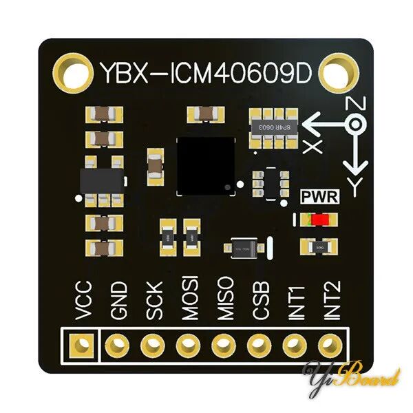
Introduction to the YBX-ICM40609D Sensor Module
The YBX-ICM40609D module uses TDK’s latest generation high-performance six-axis MEMS inertial measurement component sensor ICM-40609-D. This sensor employs advanced architectural design to enhance the performance and temperature accuracy of the IMU, making it an ideal drone solution for maintaining platform stability during prolonged flights that may experience significant temperature variations.
The maximum output data rate (ODR) of the ICM-40609-D is 32KHz, which is the best sampling rate available in consumer-grade devices. The ability to capture data at such a high ODR allows customers to easily identify any anomalies or errors that need to be addressed during flight. The full-scale range of acceleration has also been increased to 32g, enabling the tracking of substantial linear movements.
This module supports SPI and I2C interfaces for system integration, allowing for quick connections to controllers such as Arduino and STM32. The module features an onboard power chip that supports 3.3-5V power supply.
Hardware Connections
The YBX-ICM40609D sensor module is connected to the SPI1 interface of the NUCLEO-G070RB, with corresponding pins PA5 (SCK), PA6 (MISO), and PA7 (MOSI). The chip select pin CS is connected to PB2, and the INT1 pin is connected to PC7. The module’s VCC is connected to the +5V pin, and the GND pin is connected to any GND pin on the NUCLEO-G070RB.

STM32CubeMX Tool Configuration
The STM32CubeMX tool is a free software configuration tool provided by ST, offering several project templates to quickly create projects based on MCU, development boards, and example programs. Using this tool, we can quickly create a project based on the NUCLEO-G070 development board.
First, open the STM32CubeMX tool, click on ACCESS TO BOARD SELECTOR, find the NUCLEO-G070RB development board in the pop-up interface, and then click the Start Project button in the upper right corner.
In the Pinout layout, RCC, Debug, UART2, LED, and other peripherals have already been initialized.
We will use the SPI1 peripheral to connect the sensor module, setting the mode of SPI1 to Full Duplex Master, and configuring PA5, PA6, and PA7 as SPI1_SCK, SPI1_MISO, and SPI1_MOSI, respectively. Then, define PB2 as the CS output. Finally, set the SPI communication parameters according to the timing diagram in the manual.
Note that the clock frequency of SPI must not exceed 12MHz.
Finally, generate the project files based on Keil MDK.
Driver Files
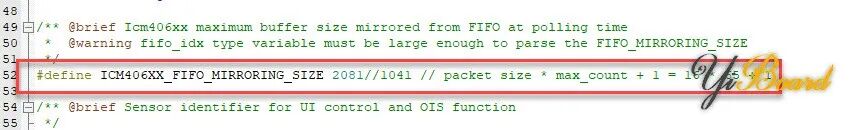
TDK has not provided driver files and example code for the ICM-40609-D, so we need to port the code. The official website provides DK-40609-D SmartMotion eMD code, which we can download and optimize for porting.
Note: The ICM406XX_FIFO_MIRRORING_SIZE in the code needs to be redefined as 2081.
Code
Open the project file and add the ported driver files to the project. The code in this article uses FIFO reading, entering an interrupt when the data area is full. Below is the code:
printf("\nICM-40609-D SPI Test\n");  printf("Bolgen Studio\n");
  inv_icm406xx_sleep_ms(1000);
  /* Initialize MCU hardware */  rc = setup_mcu(&icm406xx_serif);  check_rc(rc, "Error while setting up MCU");
  /* Initialize Icm406xx */  rc = setup_inv_device(&icm406xx_serif);  check_rc(rc, "error while setting up INV device");
  /* Configure Icm406xx */  rc = configure_inv_device((uint8_t)IS_LOW_NOISE_MODE, ICM406XX_ACCEL_CONFIG0_FS_SEL_4g,                            ICM406XX_GYRO_CONFIG0_FS_SEL_2000dps, ICM406XX_ACCEL_CONFIG0_ODR_1_KHZ,                            ICM406XX_GYRO_CONFIG0_ODR_1_KHZ);
  check_rc(rc, "error while configuring INV device");
  do  {    /* Poll device for data */    if (irq_from_device & TO_MASK(INV_GPIO_INT1))    {      rc = get_data_from_inv_device();      check_rc(rc, "error while processing FIFO");
      //      inv_disable_irq();      irq_from_device &= ~TO_MASK(INV_GPIO_INT1);      //      inv_enable_irq();    }
  } while (1);
Output Results
Upload the code to the development board, open the serial tool, set the baud rate to 115200, and data should be displayed in the serial port: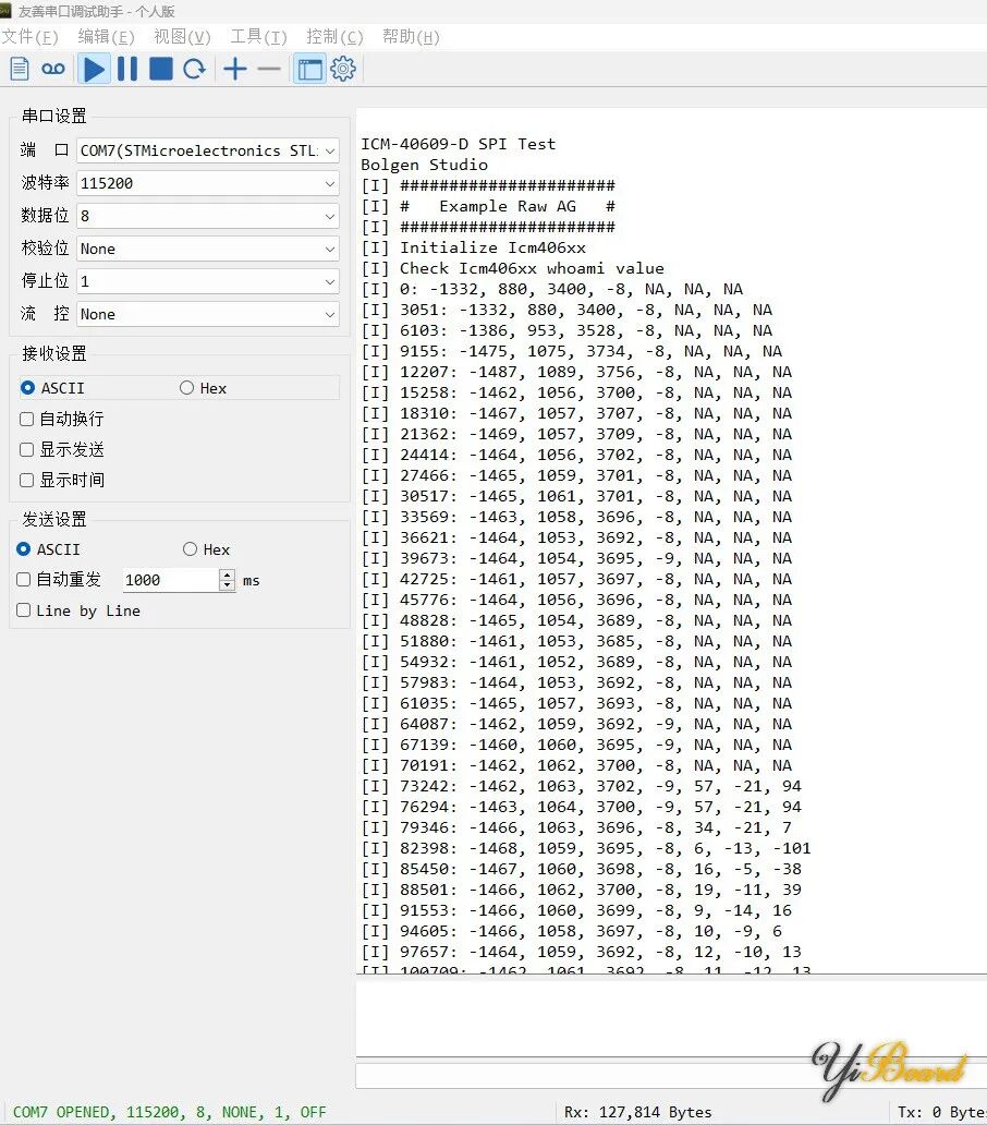
For more content, please click“Read the original text” 》》