In a display system based on MIPI DSI, the Host Controller (hereinafter referred to as HC) is an essential component. It can be integrated with other components in the following ways: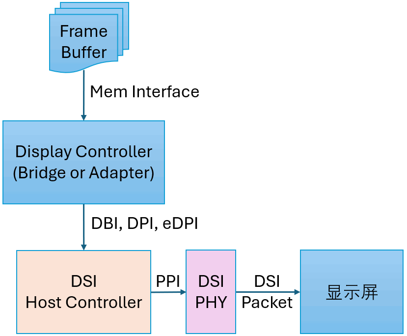 The internal structure block diagram of HC is as follows:
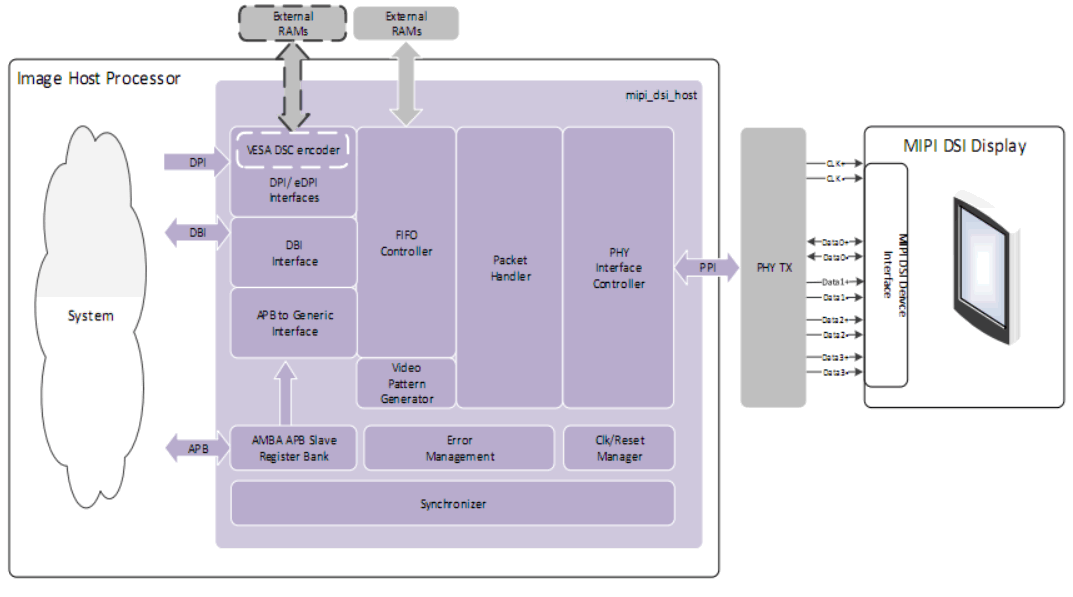 The interfaces with the “System” are: DPI, DBI, APB. As known from the meanings and differences between DPI and DBI in MIPI DSI, DPI and DBI are two methods for sending pixel data, and the choice of interface is a parameter of hardware configuration:
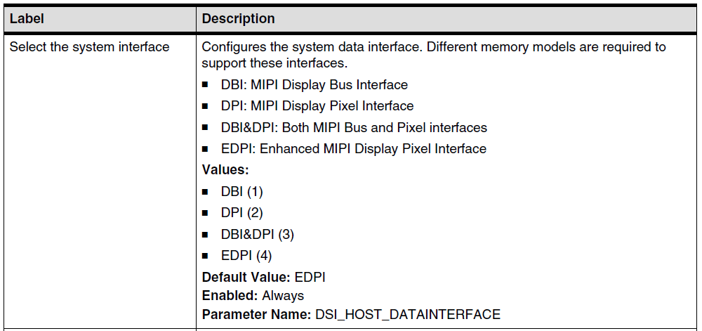 Let’s focus on eDPI, which is enhanced DPI. The enhancement lies in reusing some of the DPI pins to send memory write-related commands in DCS commands:
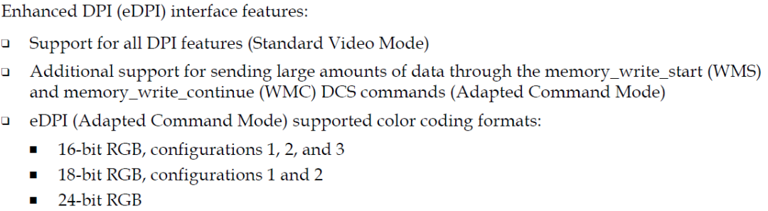 From the above, we know that eDPI has two modes:
- DPI standard Video Mode
- Private Adapted Command Mode
As shown in the figure below: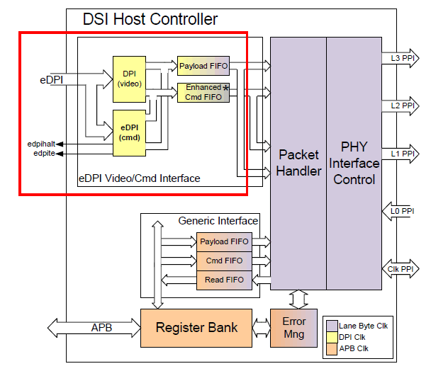 When designing a DSI display system, the upstream DPI component interfaces with the HC. The interface signal connections are as follows:
| pclk | Pixel clock |
| pclk_dsc | DSC encoder clock |
| vsync_edpiwms | Write memory start |
| vsync | Frame synchronization signal |
| hsync | Line synchronization signal |
| pixdata | A set of signals, where one pixel clock transmits one pixel value |
| pixdata2 | Same as pixdata, depending on whether the hardware parameters are configured for a second DSC Encoder |
| dataen | Data enable signal |
| shutdn | Turn off display |
| colorm | Switch between Normal Color and Reduced Color |
| updatecfg | Indicates that there is a new configuration for the next frame |
| tear_request | Activate hardware Tearing Effect |
| halt | Output signal, Halt Indication on Video Interface |
| te | Output signal, Tearing Effect Indication |
The selection of the two working modes of eDPI is controlled by the register MODE_CFG: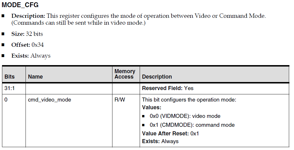 When the eDPI interface operates in Video Mode, upstream and downstream collaboration requires both parties to set timing-related information, which HC sets through a series of registers. The main process is as follows:
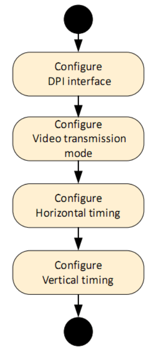 Step 1: Configure the DPI interface, mainly setting the following three registers:
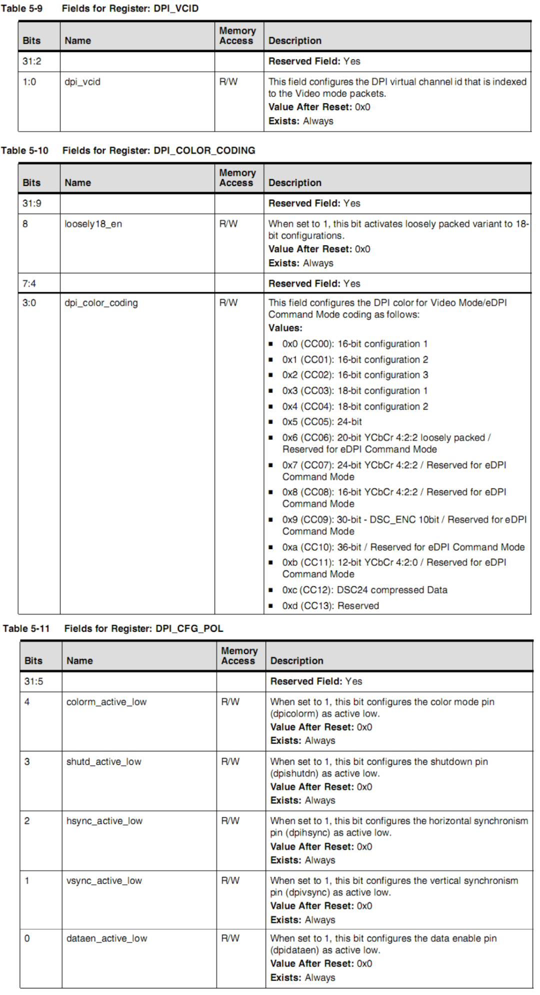 Among them, VCID sets the virtual channel identifier in the generated DSI data packet, COLOR_CODING sets the pixel encoding format transmitted over DPI, and DPI_CFG_POL sets the polarity of the DPI signal: whether it is active low or active high.Step 2: Set the VID_MODE_CFG register:
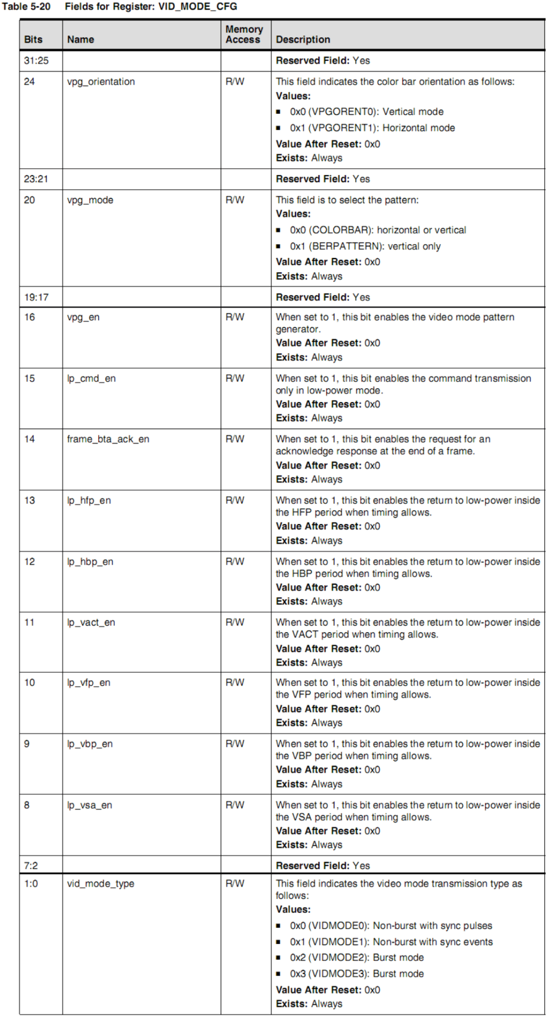 Where frame_bta_ack_en sets the request for peripheral acknowledgment message at the end of the frame,
 <span>lp_cmd_en</span><span><span> enables command transmission in low power mode, and other lp_xxx_en settings are for low power mode during transmission gaps, while vid_mode_type sets burst or non-burst mode.</span></span><span><span><span>Step 3: Set horizontal timing, the values set are the number of clock cycles in lane byte clock cycles:</span></span></span>
| VID_HSA_TIME | Horizontal Synchronism Active period in lane byte clock cycles |
| VID_HBP_TIME | Horizontal Back Porch period in lane byte clock cycles |
| VID_HLINE_TIME |
The size of the total line time (HSA + HBP + HACT + HFP) in lane byte clock cycles |
Step 4: Set vertical timing, measured in lines:
| VID_VSA_TIME |
Vertical Synchronism Active period measured in number of horizontal lines |
| VID_VBP_TIME | Vertical Back Porch period measured in number of horizontal lines |
| VID_VFP_LINES |
Vertical Front Porch period measured in number of horizontal lines |
| VID_VACTIVE_LINES |
Vertical Active period measured in number of horizontal lines |
When the eDPI interface operates in Adapted Command Mode, DCS commands WMS (Write Memory Start) and WMC (Write Memory Continue) can be sent over the eDPI interface to write display data to the screen, allowing for refreshing part of the display area in Command Mode. Only WMS and WMC commands can be sent through the eDPI interface, while other display-related configurations, readbacks, and Tearing Effect initialization commands need to be done through the HC’s APB (register read/write) interface.In Command Mode, the display data transmitted by the WMS and WMC commands on eDPI will also be cached in the HC’s Payload FIFO, while control-related data will be cached in the Command FIFO. The HC will convert the FIFO contents into DSI packets to send to the display.
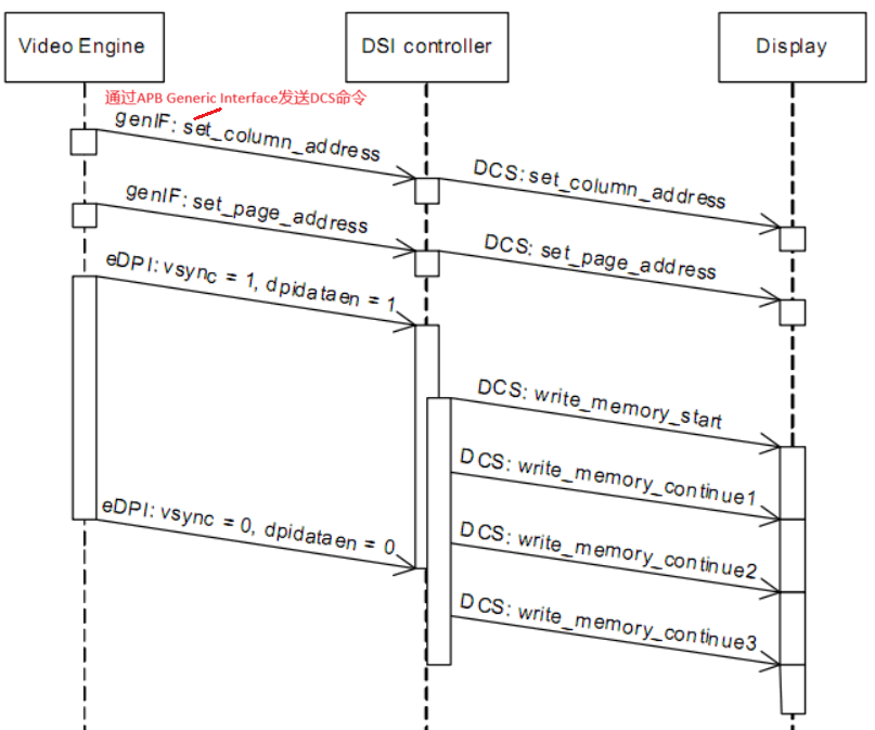
To transmit image data via the eDPI interface in Command Mode, the following steps can be followed:
-
Use the set_column_address and set_page_address DCS commands to specify the image area to be refreshed. This image area only needs to be defined once, and it remains valid until a new value is defined.
-
Determine the pixel color coding to be used through the dpi_color_coding field in the DPI_COLOR_CODING register. At the same time, set the virtual channel for the eDPI generated data packet using the dpi_vcid field in the DPI_VCID register. These two settings also only need to be done once.
-
Enable the operation to transmit data through the eDPI interface.
 As shown in the figure below, pixel data is multiplexed through dpidata[23:0]:
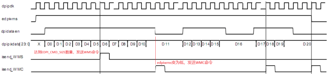 When the pixel data read from dpidata[23:0] reaches the quantity defined by the register EDPI_CMD_SIZE, a command will be written to the Command FIFO, and the corresponding DSI Packet will be sent to the display.
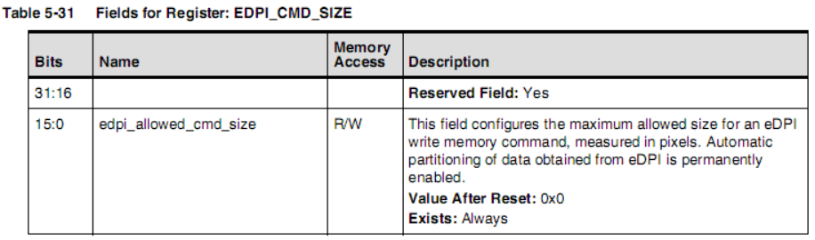 If the quantity has not yet been reached, the dpivsync_edpiwms signal will go low, writing a WMC command into the Command FIFO, and the WC field of the corresponding DSI Packet will reflect the actual number of pixels.The APB Generic Interface of HC is used to transmit DSI write command mode packets and read command mode packets through registers. The GEN_PLD_DATA register serves two different functions based on the operation. When sending Command Mode packets, writing data to this register will send it as Payload. When reading this register, it will return the Payload of the read operation. The GEN_HDR register contains the header type and header data of the Command Mode packet. Writing data to this register will trigger the transmission of the packet, meaning that for long command mode packets, the Payload of the packet needs to be written to the GEN_PLD_DATA register in advance.
Some bits in the CMD_PKT_STATUS register are used to report FIFO status related to APB interface support.