This tutorial series will start from the most basic theories and practices, detailing how to build the STM32F103C8T6 minimum system. The article will divide the minimum system into several modules for sequential introduction, thoroughly analyzing the circuit topology and the role of each component in the circuit along with reasons for their selection. This ensures that readers can enjoy a seamless learning experience. When learning embedded systems, we generally start with microcontrollers. Studying microcontrollers requires not only software knowledge but also hardware knowledge. A design that combines software and hardware is a truly excellent design.
1. What is a Minimum System?
The purpose of a minimum system is to provide a simple and cost-effective way to start developing, testing, learning, and experimenting with the STM32F103C8T6.
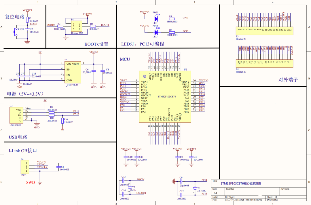
In the field of embedded systems, the minimum system (Minimal System), sometimes referred to as the minimum boot system or minimum runnable system, refers to the most basic hardware required to run a microcontroller. It is the simplest configuration that allows the microcontroller to boot and perform basic operations. It is a simplified design that can achieve the most basic functions. Taking the STM32 F103C8T6 microcontroller as an example, the minimum system consists of the following components: power supply, reset, clock, startup mode, and download debugging.
2. What is the Minimum System of STM32 F103C8T6?
The minimum system of STM32F103C8T6 consists of the following basic components:
1. STM32F103C8T6 microcontroller: As the name suggests, it is the core component.
2. Power supply: The STM32F103C8T6 requires a stable power supply of 3.3V. It can be obtained using a linear voltage regulator (like LD1117V33), a switching regulator, or directly from a stable 3.3V power source.
3. Crystal oscillator: Although the STM32F103C8T6 has an internal RC oscillator, an external 8MHz or 12MHz crystal oscillator is usually connected to ensure the stability and accuracy of the system clock. In addition to the crystal oscillator, two load capacitors matching the crystal frequency are required.
4. Reset circuit: A reset button is usually connected to the NRST pin of the microcontroller to allow manual reset. The reset pin also requires a pull-up resistor to ensure that the pin remains high when the reset button is not pressed.
6. Debug/programming interface: The STM32F103C8T6 supports JTAG and SWD interfaces, so at least the data line (SWDIO) and clock line (SWCLK), as well as GND and 3.3V, need to be connected for programming and debugging.
7. Decoupling capacitors: Small capacitors (like 100nF) are placed near the power pins of the microcontroller to filter out high-frequency noise on the power lines.
8. LED indicator (optional): Generally, there will be an LED on the minimum system board (connected to a GPIO pin through a current-limiting resistor) for basic output testing.
3. Power Section
First, let’s look at the circuit diagram:
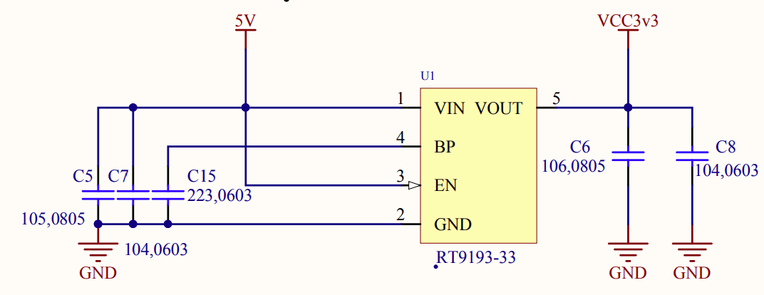
The purpose of this power circuit is to convert the externally input 5V voltage to 3.3V to power the microcontroller, with the voltage conversion component being the RT9193-33.
RT9193-33
RT9193-33 is a linear voltage regulator component produced by Richtek. Its output voltage is fixed at 3.3V, with the last two digits “33” typically representing the output voltage value. This type of regulator is widely used in applications requiring low dropout (LDO) and low power consumption.
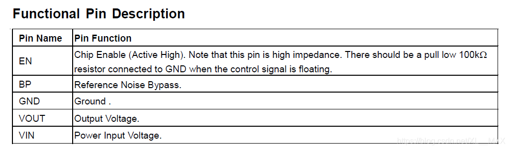
Pin definition diagram:
Features of the RT9193 series regulators include:
Low dropout: Due to its LDO characteristics, this regulator can operate normally even with a small difference between input and output voltage.
High output accuracy: The output voltage has high precision.
High efficiency: Suitable for battery-powered applications because they can operate at lower input voltages.
Low power consumption: Suitable for electronic devices sensitive to standby power consumption.
Good stability: Can provide stable voltage output for downstream circuits.
Such components are commonly used in portable devices, microcontroller power supplies, wireless communication devices, etc. They are usually packaged in various forms such as SOT-23, SOT-89, SOT-223, etc., to meet different board space requirements and power needs. In circuit design, to ensure the regulator operates normally, appropriate capacitors are usually connected at both the input and output ends.
Capacitor Analysis
For example: C5, this capacitor is marked in the schematic as: 105, 0805.
105 indicates the capacitance of the capacitor. The capacitor capacity code is a three-digit number, where the first two digits are significant figures, and the third digit is the number of zeros that follow. Therefore, in 105, 10 represents the base number, and 5 indicates that this number is followed by 5 zeros, which equals 100000 picofarads (pF), or 1.0 microfarads (uF).
0805 indicates the physical size of the capacitor. In this case, the 0805 size refers to the capacitor’s length and width of approximately 0.08 inches x 0.05 inches, or about 2.0 mm x 1.25 mm. This is a common surface mount component size.
The VIN (input voltage) and BP (Bias Pin) pins of the RT9193-33 regulator are connected to capacitors to improve circuit performance and stability. Specifically, the role of the capacitors includes:
Capacitor on VIN Pin:
– C5 `105` capacitor: This is a 1.0 microfarad (uF) capacitor that provides decoupling functionality for the VIN pin. Decoupling capacitors can smooth the input voltage, filter out high-frequency noise and voltage spikes, ensuring stable input to the regulator, allowing it to provide more stable output.
– C7 `104` capacitor: This is a 0.1 microfarad (uF, or 100 nanofarads, nF) capacitor that is usually used together with a 1.0uF capacitor to improve filtering performance, especially in the high-frequency range. This is because capacitors of different values have different filtering effects at different frequencies, and the 0.1uF capacitor is better at filtering high-frequency noise.
Why use both a large capacitor and a small capacitor?
When used as filtering elements in a circuit, the filtering effect of capacitors on different frequency signals depends on their frequency response characteristics. The impedance (Z) of a capacitor is frequency-dependent, given by the following formula:
$$\[ Z = \frac{1}{j2\pi fC} \]$$
where (Z) is the impedance, (j) is the imaginary unit, (f) is the signal frequency, and (C) is the capacitance value.
**For high-frequency signals**: – High-frequency signals make the 2πf value large.
– As f (frequency) increases, the overall impedance Z decreases.
– Therefore, for high-frequency signals, a small capacitor (with a smaller C value) has sufficiently low impedance to easily pass these signals to ground, performing the filtering function.
**For low-frequency signals**:
– Low-frequency signals make the 2πf value small.
– As f (frequency) decreases, the overall impedance Z increases.
– For low-frequency signals, only a large capacitor (with a larger C value) can provide sufficiently low impedance to direct these signals to ground.
Some clever students may ask, according to the formula, a large capacitor should be completely sufficient, why add a small capacitor?
The formula does indicate that the impedance of a capacitor is inversely proportional to its capacitance, but it is also directly proportional to frequency. Therefore, although a large capacitor has lower impedance than a small capacitor at any given frequency, at high frequencies, even a large capacitor may not have sufficiently low impedance for effective filtering.
The key issue is that the behavior of capacitors in actual circuits is not solely determined by ideal capacitive impedance. In high-frequency applications, other factors become crucial, such as the equivalent series resistance (ESR) and equivalent series inductance (ESL) of the capacitor.
The equivalent series inductance (ESL) is an important parameter of capacitors at high frequencies. All real capacitors have some inductance, which resonates with the capacitance at high frequencies. At a certain frequency point, the impedance of the capacitor reaches its minimum, known as the resonance frequency. Above this resonance frequency, the capacitor’s impedance actually increases with frequency because the inductive effects dominate.
Therefore, although large capacitors have lower impedance at low frequencies, their higher ESL limits their filtering effectiveness at high frequencies. Small capacitors typically have lower ESL, so they can work effectively at high frequencies, providing a low-impedance path to filter out high-frequency noise.
The equivalent series resistance (ESR) is another parameter affecting capacitor performance at high frequencies. ESR is the resistive component within the capacitor that causes losses. At high frequencies, ESR can lead to power loss, affecting the capacitor’s filtering performance.
In summary, due to their equivalent series inductance and resistance, large capacitors typically perform worse than small capacitors at high frequencies. Therefore, designers often use both large and small capacitors in parallel in circuits to leverage their respective advantages at different frequencies.
Capacitor on BP Pin:
– `223` capacitor: This is a 22 nanofarad (nF) capacitor. The BP pin is used to provide a bias voltage for the internal circuit, sometimes used to improve the performance of the regulator. The capacitor connected to the BP pin can help stabilize the bias voltage and reduce noise, thereby enhancing the overall performance of the regulator.
For the specific connection method and value selection of these capacitors, it is usually necessary to refer to the RT9193-33 datasheet and application notes. Manufacturers provide recommended capacitor values and types based on the characteristics of the regulator to ensure optimal performance. The selection and layout of capacitors can also be influenced by other components in the circuit design, PCB routing, and working environment.
In the design of linear regulators like the RT9193-33, the output terminal VOUT is usually connected to two capacitors of different values, one larger (e.g., 10μF, marked as 106) and one smaller (e.g., 0.1μF, marked as 104), each capacitor has its specific function:
(3) VOUT terminal capacitor analysis: The VOUT of the above RT9193-33 connects to ground through two capacitors 106 and 104, and the purpose of these large and small capacitors is not entirely the same as in the previous case,
C6 Large Capacitor (10μF, marked as 106)
1. Low-frequency filtering:
Smooths low-frequency fluctuations in the output voltage, reducing voltage ripple caused by load changes.
Provides energy storage to respond to transient load changes, helping to maintain stable output voltage.
2. Energy reserve:
Provides immediate energy demand when the load suddenly increases.
Helps stabilize output voltage when input voltage fluctuates or temporarily drops.
3. Stability support:
Assists the internal control loop of the regulator to ensure stable operation and prevent oscillation.
C8 Small Capacitor (0.1μF, marked as 104)
1. High-frequency decoupling:
Filters out high-frequency noise caused by the internal switching noise of the regulator, external circuit interference, or power line conduction.
Due to the higher self-resonant frequency of small capacitors, they have lower impedance at high frequencies, making them more effective.
2. Fast transient response:
When the load changes rapidly (e.g., when peripherals are turned on or off), small capacitors can quickly charge and discharge, helping to stabilize output voltage.
3. Improve regulator performance:
Enhances the linear regulator’s sensitivity to high-frequency noise.
Helps reduce inductive noise caused by long leads.
Using both types of capacitors in parallel is due to their complementary roles. The large capacitor primarily handles low-frequency filtering and energy storage, while the small capacitor is responsible for high-frequency decoupling and fast transient response. Additionally, small capacitors are usually placed closer to the VOUT pin of the regulator to maximize their high-frequency decoupling effect. Through this configuration, the circuit can provide stable output voltage across a wide frequency range while minimizing noise and transient effects on circuit performance.
(4) Decoupling Capacitors
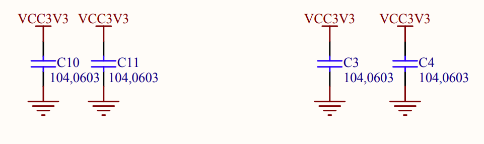
These four capacitors are connected to the four VCC pins for filtering and decoupling. The specific roles of these capacitors are as follows:
High-frequency decoupling
Power stability: The microcontroller generates high-frequency noise at its power pins during operation, which may come from internal digital switching activities, such as CPU and peripheral clock and data transfers.
Noise filtering: Multiple 0.1μF capacitors can effectively filter out these high-frequency noises, ensuring that the VCC pins of the microcontroller receive clean and stable power.
Transient response
Fast response to load changes: When the MCU’s load suddenly changes (for example, when peripherals are turned on or off), the capacitors can quickly provide or absorb charge to counteract transient voltage fluctuations.
Reduces voltage drop: These capacitors help reduce voltage drops on the power rail caused by transient loads.
Distributed decoupling
Local filtering: Distributing multiple capacitors on the circuit board can provide local decoupling at various parts of the MCU, thus reducing the impedance on the power network. Placing a 0.1μF capacitor near each VCC pin of the MCU can also ensure that each power point has nearby decoupling components, reducing lead lengths and thus minimizing inductive and radiated noise. (This is why four 104 capacitors are used.) Even if one capacitor fails, the others can still provide decoupling.
Improving electromagnetic compatibility (EMC): By reducing the power line noise caused by the MCU, overall system electromagnetic compatibility can be improved.
In design, we should also consider the physical size, cost, and availability of capacitors. Additionally, datasheets and application notes often provide specific guidelines for decoupling and filtering to ensure optimal performance.