Memory Layout in Embedded Systems: Designing Compact Apartments in Microcontrollers
As an embedded engineer, have you ever wondered how your code settles into the limited memory of a microcontroller after you upload it? Today, we will delve into the layout of embedded programs in microcontroller memory, akin to designing a compact apartment in a limited space, where every corner must be meticulously planned.
The Uniqueness of Embedded Memory
Unlike general-purpose computers, embedded systems do not have a virtual memory mechanism or a hard drive as backup storage. The memory layout of microcontrollers is more direct and compact, just like extreme planning within a limited space of tens of KB to hundreds of KB.
The Four Core Areas of Microcontroller Memory
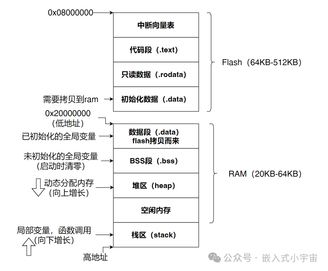
1. Flash Storage: The Permanent Residence of Programs
Characteristics: Non-volatile, Read-only, Stores all code and constants
In microcontrollers, Flash is equivalent to the program’s “permanent residence”, similar to the building blueprint and fixed decoration of an apartment.
Contents Included:
-
Program code (.text section)
-
Read-only data (const constants)
-
Interrupt vector table
-
Initialized data (needs to be copied to RAM at startup)
const uint32_t SERIAL_BAUD_RATE = 115200; // Stored in Flashvoid system_init(void) { /* Code is also in Flash */ }Embedded Characteristics:
-
Slower read speed (compared to RAM)
-
Limited write cycles (usually around 100,000 times)
-
May require wait states when executing code
2. RAM Data Area: The Workshop for Program Execution
Characteristics: Volatile, Read-write, fast but space is precious
RAM is the workshop for program execution, where all dynamically changing data is processed. For embedded systems, RAM is the most valuable resource.
2.1 Data Section (.data): Initialized Global Variables
int32_t sensor_value = 0; // Initial value copied from Flash to RAM at startupstatic uint8_t device_status = INITIALIZED;2.2 BSS Section (.bss): Uninitialized Global Variables
float temperature_buffer[100]; // Initialized to 0 at startupchar uart_tx_buffer[256];Embedded Challenges: Limited RAM space requires careful planning of each variable’s usage
Data Section (.data + .bss) – “Fixed Resident Area”
This part stores the global and static variables:
// .data section: Initialized global variablesint32_t sensor_value = 100; // Copied from Flash to RAM at startupstatic char device_name[] = "STM32";// .bss section: Uninitialized global variablesfloat temperature_buffer[100]; // Initialized to 0 at startupuint8_t comm_buffer[256];Characteristics:
-
Fixed location, size determined at compile time
-
Lifetime is the same as the program
2.3 Heap Area: The “Elastic Space” for Dynamic Memory
Characteristics: Usually used cautiously in embedded systems
Unlike general-purpose computers, the use of the heap in embedded systems requires extra caution:
// Use cautiously in resource-constrained embedded systemsvoid *dynamic_buffer = malloc(512); // May fail or cause fragmentationEmbedded Practice Recommendations:
-
Small embedded systems typically avoid dynamic memory allocation
-
Use static allocation or memory pool techniques instead
-
If used, the heap size must be explicitly defined in the linker script
Heap Area – “Free Development Zone”
The heap area is used for dynamic memory allocation, which needs to be used cautiously in embedded systems:
// Example of heap allocationvoid* dynamic_buffer = malloc(512); // Allocate from heapif (dynamic_buffer != NULL) { // Use memory... free(dynamic_buffer); // Must be manually freed!}Heap Characteristics:
-
Grows upwards: Allocated from low addresses to high addresses
-
Manual management: Requires explicit allocation and deallocation
-
Prone to fragmentation: Frequent allocation and deallocation of different sizes can lead to fragmentation
2.4 Stack Area: The “Temporary Workbench” for Function Calls
Characteristics: Automatically managed, last in first out, limited depth
The stack area is one of the most critical memory regions in embedded systems:
void process_sensor_data() { int32_t raw_value = read_adc(); // Local variable on the stack float converted = calibrate(raw_value); // Function call uses stack space // Automatically released when function returns}Embedded Key Issues:
-
Stack overflow is the most common cause of crashes in embedded systems
-
Need to reasonably estimate the maximum depth of function call chains and local variable sizes
-
Each task in a multitasking system requires independent stack space
Stack Area – “Temporary Workspace”
The stack area is used for function calls and local variables:
void process_data(void) { int32_t local_var = 10; // Allocated on the stack float temp_array[50]; // Array on the stack function_call(local_var); // Function call uses stack space // Automatically releases all local variables when function returns}Stack Characteristics:
-
Grows downwards: Uses from high addresses to low addresses
-
Automatically managed: Allocated when entering the function, automatically released when returning
-
Last in first out: The last allocated is the first released
Example of Actual Embedded Memory Layout
A typical memory map example based on the STM32F103 series:
Key Issue: Risk of Heap-Stack Collision
Since the heap grows upwards and the stack grows downwards, there is a collision risk:
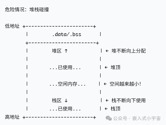
When the heap and stack meet, the system will crash!
The Secrets of the Embedded Startup Process
Key memory operations performed during microcontroller startup:
-
Initialize the stack pointer: Set the starting position of the stack
-
Copy the .data section: Copy initialized data from Flash to RAM
-
Zero the .bss section: Set uninitialized global variables to zero
-
Call the main function: The program officially runs
Typical startup file snippetReset_Handler: ldr sp, =_estack ; Set stack pointer ldr r0, =_sdata ; Start address of .data in Flash ldr r1, =_edata ; End address of .data in RAM ldr r2, =_sidata ; Start address of .data in RAM bl Memory_Copy ; Copy initialized data ldr r0, =_sbss ; Start of BSS section ldr r1, =_ebss ; End of BSS section bl Memory_Zero ; Zero the BSS section bl main ; Jump to main functionPractical Memory Management in Embedded Development
1. The Importance of Linker Scripts
Linker scripts (.ld files) are the “architectural blueprints” of embedded memory layout,linker scripts (.ld files) clearly delineate each area:
MEMORY{ RAM (xrw) : ORIGIN = 0x20000000, LENGTH = 64K}SECTIONS{ /* .data section: Initialized data */ .data : { _sdata = .; /* Start address of .data section */ *(.data) /* Contents of .data section */ _edata = .; /* End address of .data section */ } >RAM /* .bss section: Uninitialized data */ .bss : { _sbss = .; /* Start address of .bss section */ *(.bss) /* Contents of .bss section */ _ebss = .; /* End address of .bss section */ } >RAM /* Start of heap */ . = ALIGN(8); _heap_start = .; /* Start address of heap */ /* Stack definition */ _stack_size = 0x1000; /* Stack size 4KB */ _stack_end = ORIGIN(RAM) + LENGTH(RAM); /* End address of stack (end of RAM) */ _stack_start = _stack_end - _stack_size; /* Start address of stack */ /* End of heap (before stack starts) */ _heap_end = _stack_start; /* End address of heap */}2. Initialization in Startup Files
The startup file is responsible for setting the stack pointer:
Reset_Handler: /* Set stack pointer */ ldr sp, =_stack_end /* Initialize .data section (copy from Flash to RAM) */ ldr r0, =_sdata ldr r1, =_edata ldr r2, =_sidata bl memory_copy /* Zero the .bss section */ ldr r0, =_sbss ldr r1, =_ebss bl memory_zero /* Jump to main function */ bl main3. Implementation of the Heap
In embedded systems, the <span>_sbrk</span> function needs to be implemented to support heap operations:
// Heap memory management functionextern char _heap_start; /* Start of heap defined in linker script */extern char _heap_end; /* End of heap defined in linker script */char *_current_heap_pointer = &_heap_start;void *_sbrk(int incr) { char *prev_heap_pointer; /* Save current heap pointer */ prev_heap_pointer = _current_heap_pointer; /* Check if exceeds heap range */ if (_current_heap_pointer + incr > &_heap_end) { return (void*)-1; /* Out of memory */ } /* Update heap pointer */ _current_heap_pointer += incr; return (void*)prev_heap_pointer;}4. Stack Size Estimation Method// Check stack usage by filling pattern#define STACK_CANARY 0xDEADBEEFvoid stack_usage_check(void) { // Fill stack space at startup fill_stack_with_canary(); // Check maximum usage at runtime check_stack_watermark();}5. Embedded Memory Optimization Techniques
// Technique 1: Use bit fields to save spacestruct { uint8_t sensor_ready : 1; uint8_t data_valid : 1; uint8_t transmission_active : 1;} status_flags;// Technique 2: Use const and static wiselystatic const char LOG_PREFIX[] = "SYS:"; // Save RAM// Technique 3: Memory pool instead of dynamic allocation#define BUFFER_SIZE 1024static uint8_t memory_pool[BUFFER_SIZE];static size_t pool_index = 0;void* pool_alloc(size_t size) { if (pool_index + size > BUFFER_SIZE) return NULL; void* ptr = &memory_pool[pool_index]; pool_index += size; return ptr;}Common Issues and Debugging Techniques
-
Stack Overflow: Manifesting as random crashes, can be detected by filling with canary values
-
Heap Conflicts: Dynamic memory allocation leads to system instability
-
Memory Alignment: Certain architectures require specific alignment
-
DMA Conflicts: Memory area conflicts between DMA access and CPU access
Conclusion
For embedded engineers, understanding memory layout is not just theoretical knowledge, but the foundation of stability and reliability. In resource-constrained microcontroller environments, every byte of memory needs to be meticulously planned. Mastering the principles and practical techniques of memory layout can help you write more efficient and stable embedded programs.
I hope this analysis of memory layout in embedded systems is helpful for your development work. Feel free to share your embedded memory management experiences in the comments!