 Click the blue text above to subscribe!
1 Introduction
The drill bit, as one of the most commonly used cutting tools in machining, has geometric parameters that directly affect processing quality, tool life, and cutting efficiency. The core of drill tip geometric analysis lies in establishing an accurate mathematical model to calculate key angular parameters through coordinate transformation and differential geometry methods. This article elaborates on the mathematical principles of drill tip geometric parameter analysis based on research findings from a doctoral thesis at Hunan University and provides a complete C++ implementation.
2 Mathematical Foundations
2.1 Definition of Coordinate Systems
The analysis of the drill tip involves three reference coordinate systems: the structural coordinate system, the theoretical reference system, and the working reference system. The theoretical reference system is defined based on the main motion direction, and its orthogonal plane coordinate system is most suitable for analyzing the geometric parameters of the drill tip.
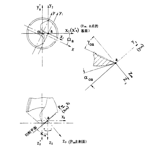
For any point on the main cutting edge, the angle between its base surface and the X-axis is:
2.2 Coordinate Transformation
Coordinate transformation is the core mathematical tool for drill tip geometric analysis. First, the original coordinate system is translated to a point, resulting in the new coordinate system:
Next, rotating around the axis by an angle results in the new coordinate system:
3 Core Geometric Parameter Calculations
3.1 Calculation of the Rake Angle
The rake angle is the angle between the base surface and the rake face, measured in the orthogonal plane. The calculation formula is:
Where the expression is the equation of the helical groove after coordinate transformation.
3.2 Calculation of the Clearance Angle
The calculation formula for the main clearance angle is:
Where the expression is the equation of the drill tip clearance face after coordinate transformation.
3.3 Calculation of the Cutting Edge Inclination Angle
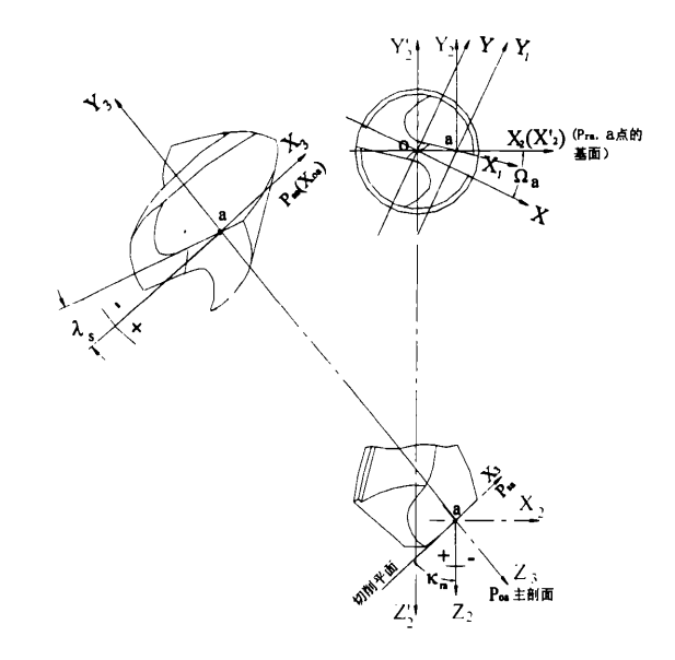
The calculation formula for the cutting edge inclination angle is:
4 C++ Implementation
4.1 Basic Data Structures
#include<iostream>
#include<cmath>
#include<functional>

const double PI = 3.14159265358979323846;

struct Point3D {
double x, y, z;
    Point3D(double x = 0, double y = 0, double z = 0) : x(x), y(y), z(z) {}

    Point3D operator+(const Point3D& other) const {
return Point3D(x + other.x, y + other.y, z + other.z);
    }

    Point3D operator-(const Point3D& other) const {
return Point3D(x - other.x, y - other.y, z - other.z);
    }

    Point3D operator*(double scalar) const {
return Point3D(x * scalar, y * scalar, z * scalar);
    }
};

struct Matrix3x3 {
double data[3][3];

    Matrix3x3() {
for (int i = 0; i < 3; i++)
for (int j = 0; j < 3; j++)
                data[i][j] = (i == j) ? 1.0 : 0.0;
    }

    Matrix3x3(double a11, double a12, double a13,
double a21, double a22, double a23,
double a31, double a32, double a33) {
        data[0][0] = a11; data[0][1] = a12; data[0][2] = a13;
        data[1][0] = a21; data[1][1] = a22; data[1][2] = a23;
        data[2][0] = a31; data[2][1] = a32; data[2][2] = a33;
    }

    Point3D operator*(const Point3D& vec) const {
return Point3D(
            data[0][0] * vec.x + data[0][1] * vec.y + data[0][2] * vec.z,
            data[1][0] * vec.x + data[1][1] * vec.y + data[1][2] * vec.z,
            data[2][0] * vec.x + data[2][1] * vec.y + data[2][2] * vec.z
        );
    }

    Matrix3x3 operator*(const Matrix3x3& other) const {
        Matrix3x3 result;
for (int i = 0; i < 3; i++) {
for (int j = 0; j < 3; j++) {
                result.data[i][j] = 0;
for (int k = 0; k < 3; k++) {
                    result.data[i][j] += data[i][k] * other.data[k][j];
                }
            }
        }
return result;
    }
};
4.2 Calculation of Partial Derivatives
class DerivativeCalculator {
public:
static double partialDerivative(const std::function<double(Point3D)>& func,
const Point3D& p, char variable, double h = 1e-5) {
        Point3D p1 = p, p2 = p;

switch (variable) {
case 'x':
                p1.x -= h;
                p2.x += h;
break;
case 'y':
                p1.y -= h;
                p2.y += h;
break;
case 'z':
                p1.z -= h;
                p2.z += h;
break;
default:
return 0;
        }

return (func(p2) - func(p1)) / (2 * h);
    }
};
4.3 Implementation of Coordinate Transformation
class CoordinateTransformer {
public:
static Matrix3x3 createRotationZ(double angle) {
return Matrix3x3(
cos(angle), -sin(angle), 0,
sin(angle), cos(angle), 0,
0, 0, 1
        );
    }

static Matrix3x3 createRotationY(double angle) {
return Matrix3x3(
cos(angle), 0, sin(angle),
0, 1, 0,
            -sin(angle), 0, cos(angle)
        );
    }

static Point3D transformToLocal(const Point3D& point, const Point3D& origin, double omega) {
        Matrix3x3 rotZ = createRotationZ(omega);
        Point3D translated = point - origin;
return rotZ * translated;
    }

static Point3D transformToSection(const Point3D& point, const Point3D& origin,
double omega, double kra) {
        Matrix3x3 rotZ = createRotationZ(omega);
        Matrix3x3 rotY = createRotationY(PI / 2 - kra);
        Matrix3x3 totalTransform = rotY * rotZ;
        Point3D translated = point - origin;
return totalTransform * translated;
    }
};
4.4 Drill Tip Geometry Analysis Class
class DrillPointAnalyzer {
private:
std::function<double(Point3D)> F1; // Clearance face equation
std::function<double(Point3D)> F5; // Helical groove equation
std::function<double(Point3D)> F6; // Rake face equation

public:
    DrillPointAnalyzer(
const std::function<double(Point3D)>& f1,
const std::function<double(Point3D)>& f5,
const std::function<double(Point3D)>& f6
    ) : F1(f1), F5(f5), F6(f6) {}

double calculateOmegaA(const Point3D& a) {
return atan2(a.y, a.x);
    }

double calculateKra(const Point3D& a) {
double omega = calculateOmegaA(a);

// Create transformed functions
auto F12 = [&](Point3D p) {
            Point3D transformed = CoordinateTransformer::transformToLocal(p, a, omega);
return F1(transformed);
        };

auto F52 = [&](Point3D p) {
            Point3D transformed = CoordinateTransformer::transformToLocal(p, a, omega);
return F5(transformed);
        };

        Point3D a_local = CoordinateTransformer::transformToLocal(a, a, omega);

// Calculate partial derivatives
double dF12_dy2 = DerivativeCalculator::partialDerivative(F12, a_local, 'y');
double dF12_dz2 = DerivativeCalculator::partialDerivative(F12, a_local, 'z');
double dF52_dy2 = DerivativeCalculator::partialDerivative(F52, a_local, 'y');
double dF52_dz2 = DerivativeCalculator::partialDerivative(F52, a_local, 'z');
double dF12_dx2 = DerivativeCalculator::partialDerivative(F12, a_local, 'x');
double dF52_dx2 = DerivativeCalculator::partialDerivative(F52, a_local, 'x');

double numerator = dF12_dy2 * dF52_dz2 - dF12_dz2 * dF52_dy2;
double denominator = dF12_dx2 * dF52_dy2 - dF12_dy2 * dF52_dx2;

return atan2(numerator, denominator);
    }

double calculateGammaOA(const Point3D& a) {
double omega = calculateOmegaA(a);
double kra = calculateKra(a);

auto F53 = [&](Point3D p) {
            Point3D transformed = CoordinateTransformer::transformToSection(p, a, omega, kra);
return F5(transformed);
        };

        Point3D a_section = CoordinateTransformer::transformToSection(a, a, omega, kra);

double dF53_dy3 = DerivativeCalculator::partialDerivative(F53, a_section, 'y');
double dF53_dz3 = DerivativeCalculator::partialDerivative(F53, a_section, 'z');

return atan2(dF53_dy3, dF53_dz3);
    }

double calculateAlphaOA(const Point3D& a) {
double omega = calculateOmegaA(a);
double kra = calculateKra(a);

auto F13 = [&](Point3D p) {
            Point3D transformed = CoordinateTransformer::transformToSection(p, a, omega, kra);
return F1(transformed);
        };

        Point3D a_section = CoordinateTransformer::transformToSection(a, a, omega, kra);

double dF13_dx3 = DerivativeCalculator::partialDerivative(F13, a_section, 'x');
double dF13_dz3 = DerivativeCalculator::partialDerivative(F13, a_section, 'z');

return atan2(dF13_dx3, dF13_dz3);
    }

double calculateLambdaS(const Point3D& a) {
double omega = calculateOmegaA(a);
double kra = calculateKra(a);

auto F13 = [&](Point3D p) {
            Point3D transformed = CoordinateTransformer::transformToSection(p, a, omega, kra);
return F1(transformed);
        };

auto F53 = [&](Point3D p) {
            Point3D transformed = CoordinateTransformer::transformToSection(p, a, omega, kra);
return F5(transformed);
        };

        Point3D a_section = CoordinateTransformer::transformToSection(a, a, omega, kra);

double dF53_dy3 = DerivativeCalculator::partialDerivative(F53, a_section, 'y');
double dF53_dz3 = DerivativeCalculator::partialDerivative(F53, a_section, 'z');
double dF13_dy3 = DerivativeCalculator::partialDerivative(F13, a_section, 'y');
double dF13_dz3 = DerivativeCalculator::partialDerivative(F13, a_section, 'z');
double dF53_dx3 = DerivativeCalculator::partialDerivative(F53, a_section, 'x');
double dF13_dx3 = DerivativeCalculator::partialDerivative(F13, a_section, 'x');

double numerator = dF53_dy3 * dF13_dz3 - dF53_dz3 * dF13_dy3;
double denominator = dF53_dx3 * dF13_dz3 - dF53_dz3 * dF13_dx3;

return atan2(numerator, denominator);
    }
};
4.5 Complete Example Program
#include<iostream>
#include<cmath>
#include<functional>

// Insert all previously defined structures and classes here

int main() {
// Define example equations - in actual applications, replace with real drill tip equations
auto F1 = [](Point3D p) {
// Example clearance face equation: plane equation
return 2.0 * p.x + 3.0 * p.y - p.z + 1.0;
    };

auto F5 = [](Point3D p) {
// Example helical groove equation: quadratic surface
return p.x * p.x + 2.0 * p.y * p.y - 0.5 * p.z;
    };

auto F6 = [](Point3D p) {
// Example rake face equation: plane equation
return p.x - 2.0 * p.y + 3.0 * p.z - 2.0;
    };

// Create analyzer instance
DrillPointAnalyzer analyzer(F1, F5, F6);

// Select a point on the main cutting edge
Point3D a(1.0, 0.5, 0.3);

// Calculate various geometric parameters
try {
double omega_a = analyzer.calculateOmegaA(a);
double kra = analyzer.calculateKra(a);
double gamma_oa = analyzer.calculateGammaOA(a);
double alpha_oa = analyzer.calculateAlphaOA(a);
double lambda_s = analyzer.calculateLambdaS(a);

// Output results (convert radians to degrees)
std::cout << "Drill tip geometric parameter analysis results:" << std::endl;
std::cout << "Point a(" << a.x << ", " << a.y << ", " << a.z << ")" << std::endl;
std::cout << "Ωa: " << omega_a * 180 / PI << "°" << std::endl;
std::cout << "Kra: " << kra * 180 / PI << "°" << std::endl;
std::cout << "γoa: " << gamma_oa * 180 / PI << "°" << std::endl;
std::cout << "αoa: " << alpha_oa * 180 / PI << "°" << std::endl;
std::cout << "λs: " << lambda_s * 180 / PI << "°" << std::endl;

// Parameter influence analysis
std::cout << "\nParameter influence analysis:" << std::endl;
std::cout << "1. Rake angle γoa affects chip formation and cutting force" << std::endl;
std::cout << "2. Clearance angle αoa affects friction between the clearance face and the workpiece" << std::endl;
std::cout << "3. Cutting edge inclination angle λs affects chip flow direction and tip strength" << std::endl;

    } catch (const std::exception& e) {
std::cerr << "Calculation error: " << e.what() << std::endl;
return 1;
    }

return 0;
}
5 Algorithm Analysis and Optimization
5.1 Considerations for Numerical Stability
The calculation of partial derivatives uses the central difference method, with an error of . The choice of step size needs to balance precision and numerical stability. A step size that is too small can lead to increased rounding errors, while a step size that is too large can reduce calculation accuracy.
5.2 Complexity Analysis
The calculation of each geometric parameter requires multiple coordinate transformations and partial derivative calculations, with a time complexity of , but the constant factor is relatively large. For cases requiring analysis of the entire cutting edge, parallel computing can be used to optimize performance.
5.3 Practical Application Recommendations
- Equation Definition: In practical applications, accurate definitions of the equations for the specific geometric shapes of the drill bit are required.
- Parameter Validation: Validate the accuracy of calculation results by comparing them with experimental measurements.
- Visualization: Combine calculation results with CAD models to achieve visual analysis of geometric parameters.
6 Conclusion
This article implements precise calculations of drill tip geometric parameters based on the principles of differential geometry and coordinate transformation. The provided C++ code fully implements the calculation algorithms for key parameters such as rake angle, clearance angle, and cutting edge inclination angle, providing a theoretical basis and practical tools for drill bit design and optimization. In practical applications, the equations in the mathematical model need to be adjusted according to the specific geometric shapes of the drill bit, and the accuracy of the calculation results should be verified through experiments.
This method is not only applicable to standard twist drills but can also be extended to the geometric analysis of various new drill tip designs, providing strong support for theoretical research and engineering applications in drilling processes.
References:Zhou Zhixiong. Research on a New Type of Drill Bit and Its Grinding Technology [D]. Changsha: Hunan University, 2000.
Note: The above code has not been verified and is for reference only.
 • end •
Companionship is the longest confession of love
We push the most practical information for you

Scan the QR code to follow us