The automotive generator is the main power source of a vehicle, functioning to supply power to all electrical devices (excluding the starter) while charging the battery during normal engine operation.

The purpose of testing the current and voltage of the automotive generator is to assess the charging rate of the generator, which is related to the electronic load placed on the battery. Any charge consumed from the battery must be replenished by the generator. The output of the generator is specified and must not be undercharged or overcharged.
For 12V series generators, the specified output voltage is 14V. For 24V series generators, the specified output voltage is 28V.
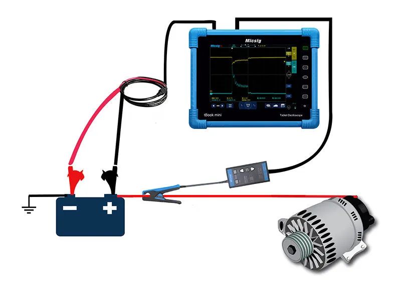
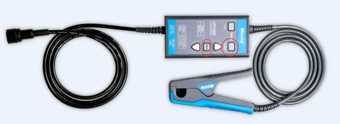
Channel one of the oscilloscope is connected to a BNC to banana plug cable, with the red alligator clip attached to the positive terminal of the battery and the black clip to the negative terminal. Channel two is connected using a current probe set to 100A. Press ZERO for automatic zeroing.
Start the engine and turn on the electronic accessories (such as headlights and heater). Some vehicles may require the engine to run for 60 seconds or longer before charging begins. In actual testing, this depends on the specific vehicle. Many newer models have adopted linear voltage output regulation for the generator, and some hybrid vehicles have eliminated traditional generators, which will not be discussed in this article.
Open the automotive repair test package on the oscilloscope, select the charging/start circuit, then choose the corresponding 12V or 24V charging option, and click OK to measure the waveform.
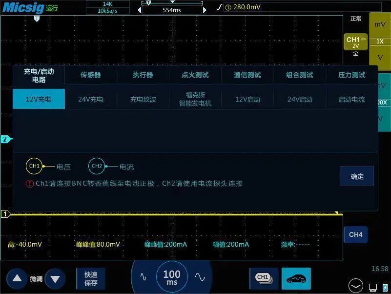
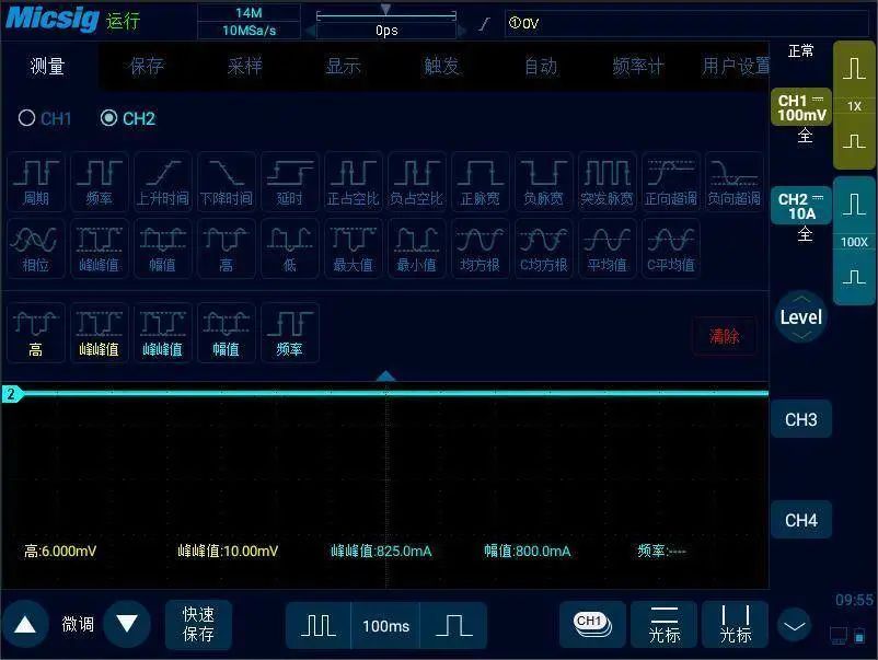
The measurement items at the bottom of the oscilloscope will automatically display the high value and peak-to-peak value of the generator voltage on channel one, and the peak-to-peak value, amplitude, and frequency of the generator current on channel two.
If the oscilloscope does not have automotive repair testing software, we will need to set it up manually.
First, set the time base of the oscilloscope to 100ms, then set the probe attenuation ratio of channel one to 1X, ensuring that the coupling mode is set to DC coupling and the probe type is set to voltage.
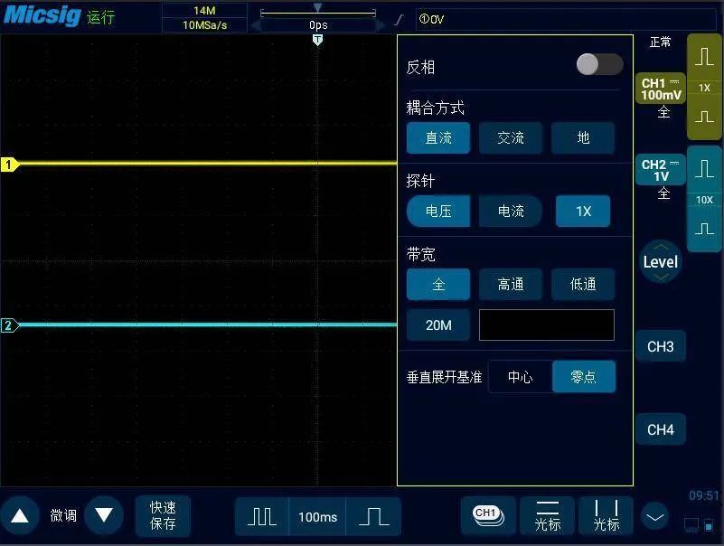
Channel two should be adjusted according to the current probe used, with the probe type set to current and the coupling mode also set to DC.
Then, following the previous connection method, connect the probes to observe the current and voltage waveforms of the automotive generator on the oscilloscope.
Finally, we can open the measurement options on the oscilloscope and select the desired measurement items for observation.
A good charging system will show that a decrease in battery voltage is accompanied by an increase in charging current, and vice versa. The rectified voltage can be measured with a multimeter, but if the generator has a failed diode causing a 33% reduction in output, the multimeter reading may still appear normal. The only correct way to monitor the generator output is to observe its voltage and current waveforms with an oscilloscope.
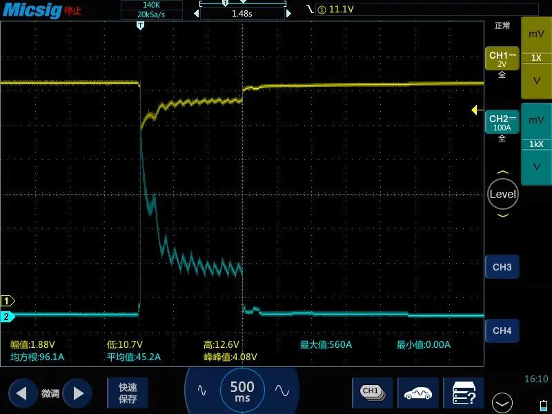
The following image shows the starting voltage and current of a Mazda measured with a 1KX attenuation current probe.
【End】