The multimeter distinguishes between live and neutral wires.
Pointer Multimeter Distinguishes Live and Neutral Wires
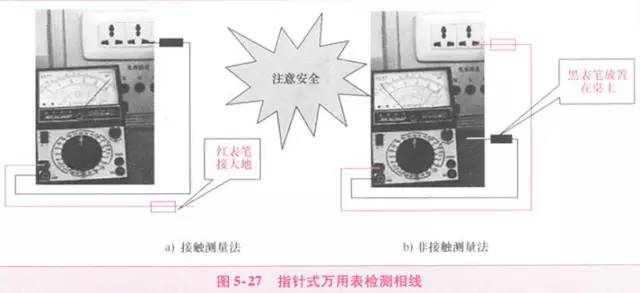
(1) Contact Measurement Method
Set the multimeter switch to AC 250V or 500V. Connect the first probe to one end of the power supply and the second probe to ground (for example, on a water pipe, radiator, or damp ground). If the grounding is good, when the multimeter reads around 220V, the first probe is connected to the live wire, as shown in Figure 5-27(a). If the pointer does not move, it indicates that the first probe is connected to the neutral wire. Even if the second probe has a high ground resistance, the pointer will show a significant deflection when the first probe is connected to the live wire.
(2) Non-contact Measurement Method
Set the multimeter switch to AC 250V or 500V. Connect the first probe to either end of the power supply, and place the second probe in the air on a table, holding the insulated part of the second probe (make sure your hand does not touch the conductive part). If the first probe is connected to the live wire, the pointer on the meter will generally deflect 2 to 10 divisions, as shown in Figure 5-27(b). The higher the sensitivity of the multimeter, the more significant the deflection. If the first probe is connected to the neutral wire, the pointer will not deflect.
Important Reminder:
This method is applicable to any model of multimeter. This method poses no danger to the human body. Because the internal resistance of a pointer multimeter is 20K/V, if used to measure 220V voltage, the internal resistance of the pointer meter is 20K × 220V = 4400, which is relatively safe.
(3) Precautions for Using Pointer Multimeter to Distinguish Live and Neutral Wires
It is best to use a test pen to distinguish between live and neutral wires in mains electricity; this is a quick and safe method.
When using a pointer multimeter to distinguish between live and neutral wires, safety must be a priority. Specifically, the insulation of the probe wires must be good, and no part of the operator’s hand or body should come into direct contact with the metal part of the probe to avoid electric shock hazards.
Digital Multimeter for Distinguishing Live and Neutral Wires
As we know, the sensitivity of the AC voltage range on a digital multimeter is very high. It can display even weak voltage signals on the LCD screen. Using the ACV range on a digital multimeter to find the live wire of AC mains electricity is intuitive, rapid, accurate, and safe.
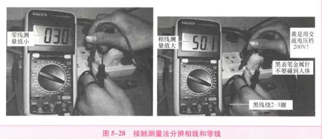
(1) Contact Measurement Method
Set the digital multimeter to the AC 20V range (or AC 2V range), remove the black probe, insert the black probe into the V/Ω socket, hold the insulated handle of the red probe with one hand, and touch the two sockets in turn with the probe tip. The socket with the larger display value is the live wire, as shown in Figure 5-28.
(2) Non-contact Measurement Method
Sometimes, we need to find the live wire from outdoor lighting lines; at this time, there is no need to strip the insulation from the wire. Use the red probe to touch the insulated outer skin of the two wires in turn, and the one with the larger reading is the live wire; since it is induced voltage, it is best to select the AC 2V range.
Using a Multimeter to Test Lighting Circuits and Devices
When testing lighting circuits and devices, it is generally done using the resistance range to measure the continuity of the circuit and to preliminarily measure the insulation status of the circuit and devices; using the AC voltage range to check whether there is voltage in the circuit or devices and whether the voltage is normal.
Measuring Circuit Resistance with Resistance Range
Electrical circuits and various circuits related to electricity can be measured using the resistance range of the multimeter. Due to the safety, convenience, and ease of resistance testing, it is highly regarded by circuit designers and maintenance personnel. By testing the resistance value of the circuit, it can be determined whether the circuit is open or shorted; by comparing the normal resistance value of components with the resistance value during faults, the condition of the components can be determined.
When testing the resistance of lighting circuits and devices, the tested device should be disconnected from the power supply before testing.
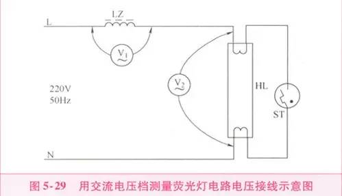
Measuring Circuit Voltage with AC Voltage Range
When repairing lighting circuits and electrical appliances, measuring the voltage value of the circuit can help analyze the cause of the fault, such as faults caused by excessively high or low supply voltage.
Figure 5-29 shows a wiring diagram for measuring the voltage of a fluorescent lamp circuit.
Using a Multimeter to Detect Short Circuit Faults in Lighting Circuits
Fault Phenomena and Causes
When there is a short circuit in the lighting circuit, the circuit current is very high, the fuse quickly blows, and the circuit is cut off. If the fuse is too thick, it can burn the wire and even cause a fire.
Possible causes of a short circuit in the lighting circuit: incorrect wiring, live and neutral wires touching; damage to the insulation layer of the wire, causing contact or grounding at the damaged area; internal damage to electrical appliances; loose lamp sockets causing metal pieces to touch and short circuit, water entering the lamp socket, etc.
Using a Multimeter to Find Short Circuit Faults
The fault phenomena of short circuits in lighting circuits are relatively obvious, but determining the location of the fault is more complex. We can use the resistance method to check where the fault is located.
The resistance method involves using the resistance range of the multimeter to measure the resistance values between wires or electrical appliances to determine the location of the short circuit. After a short circuit occurs, disconnect the knife switch (or circuit breaker) on the distribution board and unplug all electrical appliances, completely cutting off the power supply. Set the multimeter to the R×100 range and measure the resistance value between the live and neutral wires. If the pointer tends toward zero (or deflects), it indicates that there is a short circuit (or leakage) in the circuit. Check the main line and each branch line section by section, and if necessary, disconnect a certain line and measure the resistance between the two wires to determine the location of the fault.
Important Reminder:
During repairs, first find the short circuit point. You can use the resistance range of the multimeter to perform circuit segmentation and area checks in a powered-off state. Start from the load end and check step by step towards the front end to see whether the problem is caused by the circuit or the components, and you can determine it. After excluding the short circuit fault point, install a qualified fuse and restore power.
Using a Multimeter to Detect Open Circuit Faults in Lighting Circuits
Fault Phenomena and Causes
When there is an open circuit in the lighting circuit, there is no voltage in the circuit, the lighting lamp does not light, and electrical appliances cannot work. The reasons include: fuse blown, wire open circuit, loose wire ends, switch damage, etc.
Repairing Open Circuit Faults
When using a multimeter to detect open circuit faults in lighting circuits, in a powered-off state, you can use the resistance range of the multimeter to measure the continuity of the circuit; or in a powered state, you can use the AC voltage range of the multimeter to measure the voltage of the circuit to determine the fault point.
Open circuit faults in lighting circuits can be divided into three situations: complete open circuit, partial open circuit, and individual open circuit.
(1) Complete Open Circuit.
This type of fault mainly occurs on the main line, within the distribution and metering devices, and in the range of the incoming installation. Generally, the first step is to check each connection point of the above-mentioned parts in sequence (including fuse connection posts), with the most common fault being the wire end detaching from the connection point; secondly, check the operation and disconnection of the moving and static contacts of the switches in each line.
(2) Partial Open Circuit.
This type of fault mainly occurs within the branch circuit range. Generally, check each wire end connection point first, then check the branch switch. If the cross-section of the branch wire is small, consider that the core wire may break inside the insulation layer, causing a partial open circuit.
(3) Individual Open Circuit.
This type of fault is generally limited to the range of junction boxes, lamp holders, lamp switches, and the connecting wires between them. Usually, you can check each connection point separately, as well as the contact conditions of components like lamp holders, lamp switches, and sockets (for fluorescent lamps, check the connection of each component).
Using a Multimeter to Detect Leakage Faults in Lighting Circuits
Causes of Leakage in Lighting Circuits
Once leakage occurs in the lighting circuit, it not only wastes electricity but may also cause electric shock accidents. Leakage and short circuit are essentially the same; only the degree of accident development is different. Severe leakage may lead to a short circuit. Therefore, one should not take leakage in lighting circuits lightly. Regularly check the insulation condition of the circuit, especially when leakage is detected, and promptly identify the cause, locate the fault point, and eliminate it.
The main causes of leakage in lighting circuits are: First, the insulation of wires or electrical equipment is damaged by external forces; second, the insulation deteriorates due to long-term operation; third, the circuit is affected by moisture or pollution, resulting in poor insulation.
Repairing Leakage Faults
First, determine whether there is indeed leakage. You can use the R×10k range of the pointer multimeter to measure the size of the circuit’s insulation resistance, or set the digital multimeter to the AC current range (this acts as a current meter), connecting it in series with the main switch, turning on all switches, and removing all loads (including light bulbs). If there is current, it indicates the presence of leakage. Once leakage is confirmed, you can continue checking according to the following steps.
(1) Determine whether the leakage is between the live wire and neutral wire or between the live wire and ground, or both. The method is to cut off the neutral wire; if the current meter reading remains unchanged, it indicates leakage between the live wire and ground; if the current meter reading is zero, it indicates leakage between the live wire and neutral wire; if the current meter reading decreases but is not zero, it indicates leakage between the live wire and neutral wire and between the live wire and ground.
(2) Determine the leakage range. Remove the branch fuse or open the circuit breaker; if the current meter reading remains unchanged, it indicates leakage in the main line; if the current meter reading is zero, it indicates branch leakage; if the current meter reading decreases but is not zero, it indicates leakage in both the main line and branch.
(3) Locate the leakage point. After the above checks, sequentially disconnect the switches of the lighting fixtures on the circuit. When disconnecting a certain switch causes the current meter reading to return to zero, it indicates that this branch line has leakage; if it decreases, it indicates that this branch line has leakage and there are leaks elsewhere; if the current meter reading remains unchanged after all lighting fixture switches are disconnected, it indicates that the main line has leakage. Gradually narrow down the scope of the incident to further check if there is leakage at the junctions of the line and at points where the wire passes through walls. Once the leakage point is found, it should be promptly eliminated.
Important Reminder:
Short circuits, open circuits, and leakage in lighting circuits are the most common faults. Only by conducting specific measurements and analysis can we accurately find the fault points, determine the nature of the faults, and take effective measures to eliminate the faults as soon as possible.
Source: WeChat “Mechanical Industry Press E-View”
Share with friends to learn together!
Reply with the followingkeywordsto get related articles
Mastering 485 Proximity Switch Multimeter Electrician Cable Selection Free Class PLCVideo PreviewInverter Control Electrician Mnemonics
Click “Read the original text” for more exciting content