
Electricians and welders are specialized occupations, and those engaged in related work must hold a certification. Special operations certificates need to be re-evaluated every three years. One certificate per person is required, and it is valid nationwide.
Exam format: personal reference, single person at a table, divided into theoretical and practical subjects, with full marks of 100 and passing marks of 80.
Enrollment Consultation: 18206863120 (WeChat same number)
Digital Multimeter and Analog Multimeter: Transistor Measurement Guide
1. Measuring with a Digital Multimeter
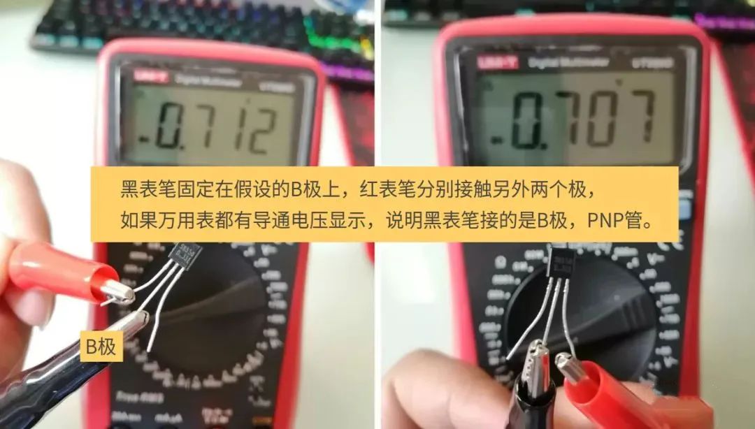
When using a digital multimeter for measurement, the “diode mode” is used. The red probe corresponds to the positive terminal of the battery, and the black probe corresponds to the negative terminal.
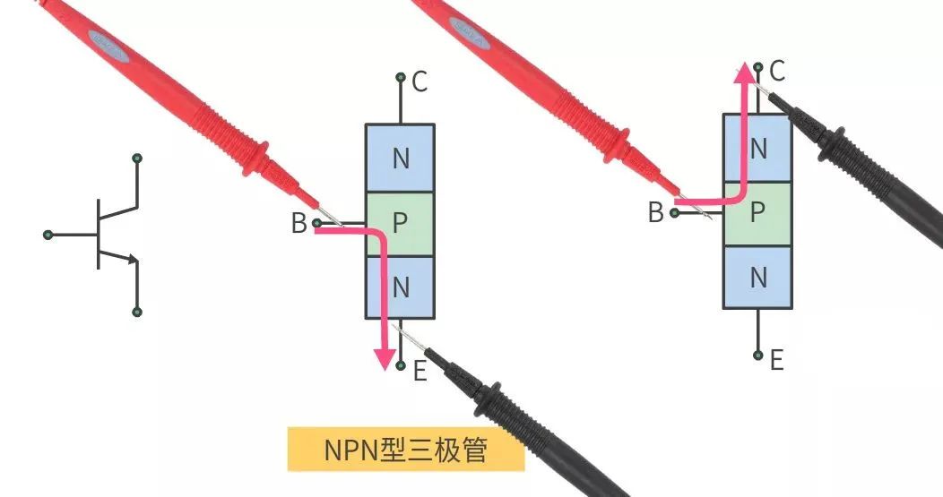
▲ NPN type, the B terminal connected to the red probe, and the black probe connected to C and E will conduct
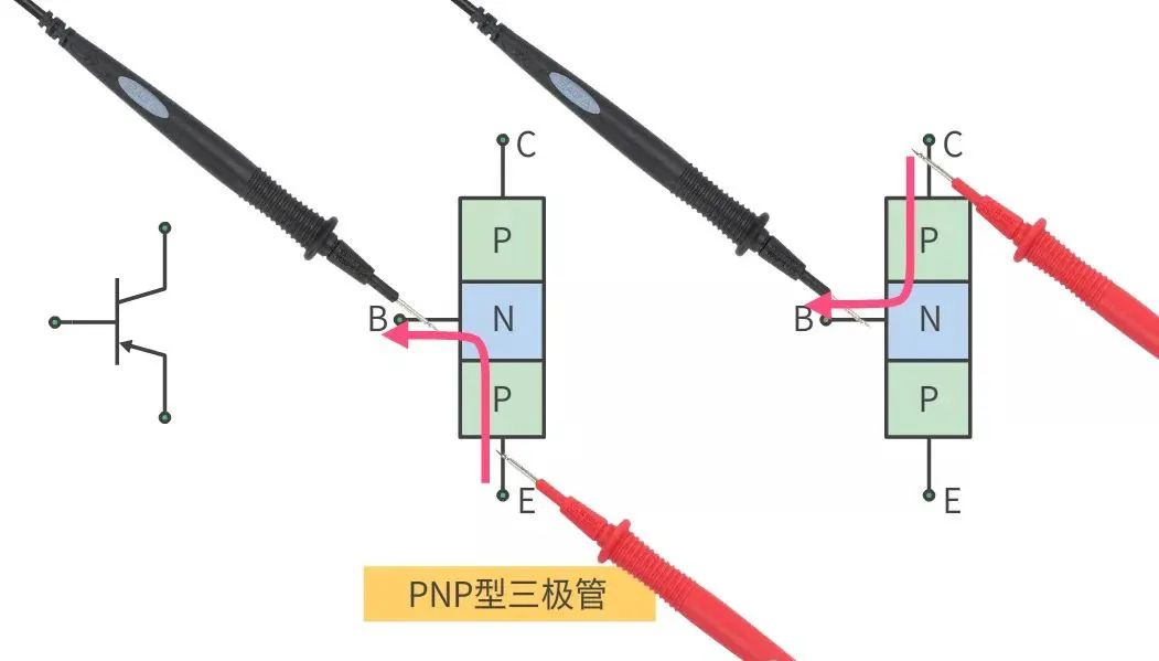
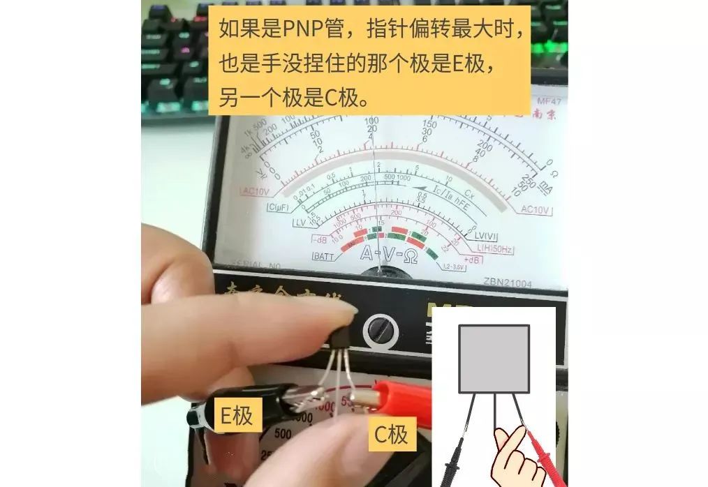
▲ PNP type, the B terminal connected to the black probe, and the red probe connected to C and E will conduct
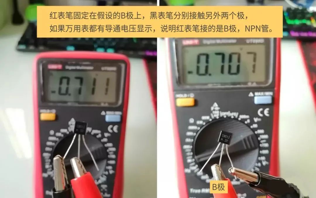
If both measurements do not show conduction, you can swap the probes and measure again until the B terminal is found.
If the conduction voltage displayed during measurement is 0V, it indicates that the transistor has broken down and is damaged.
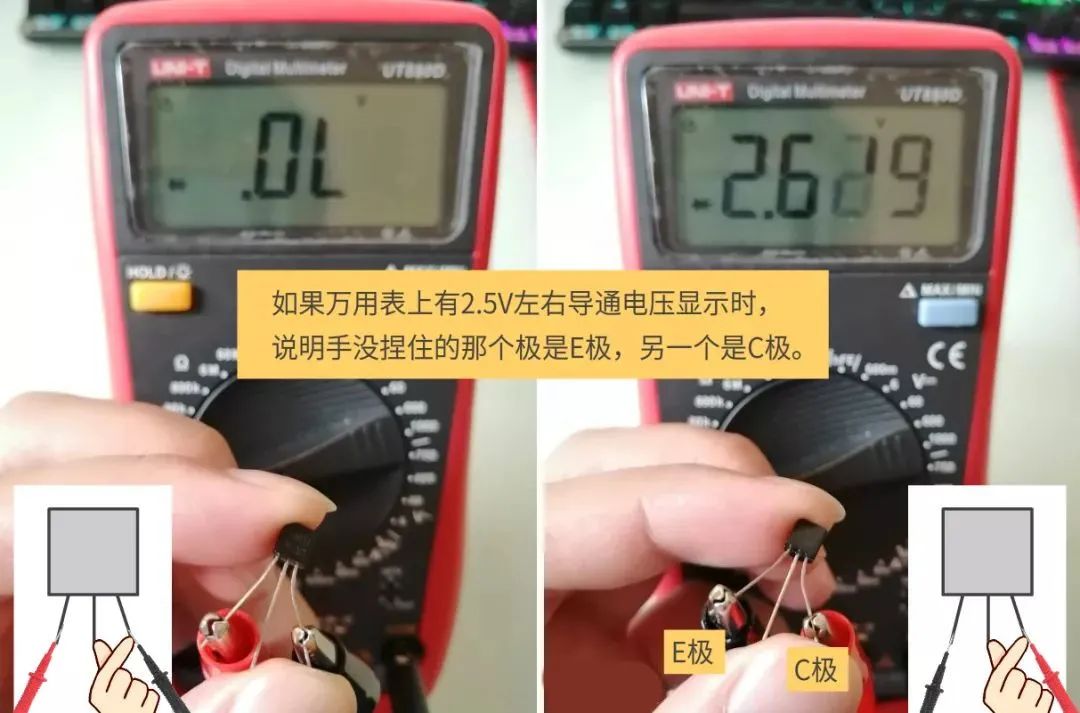
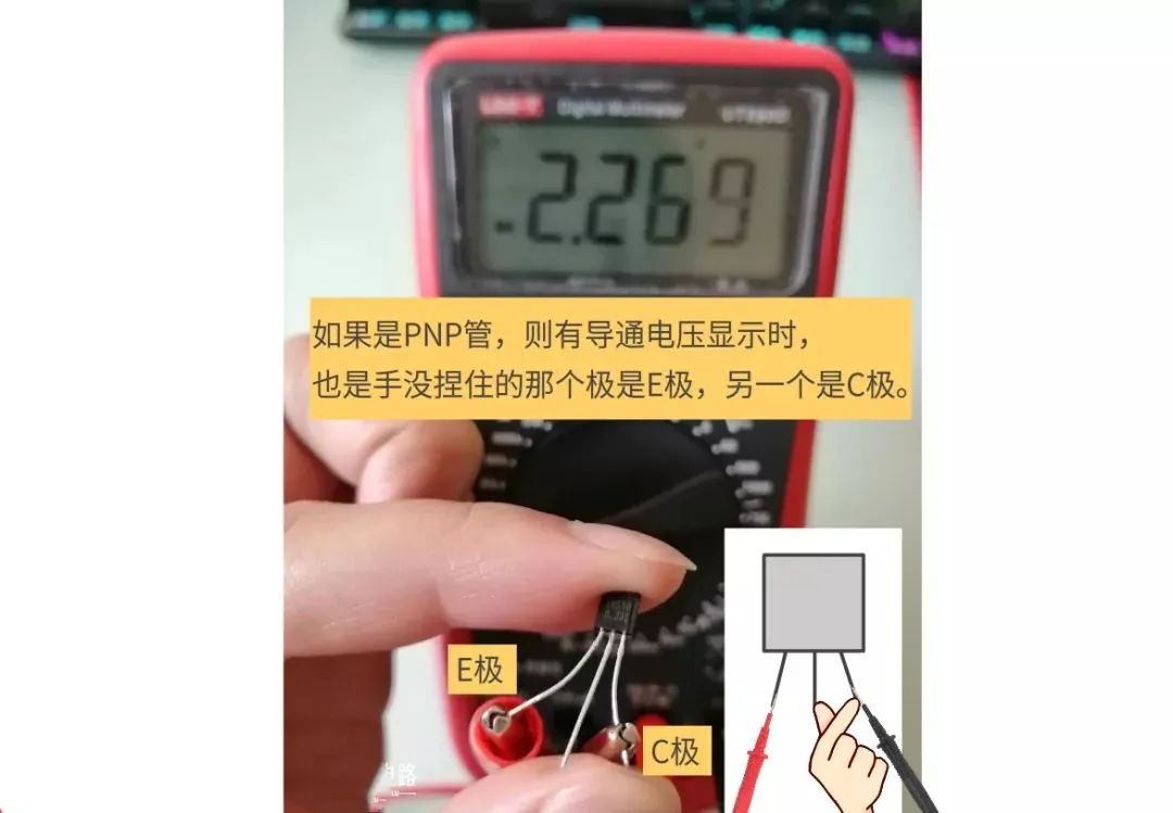
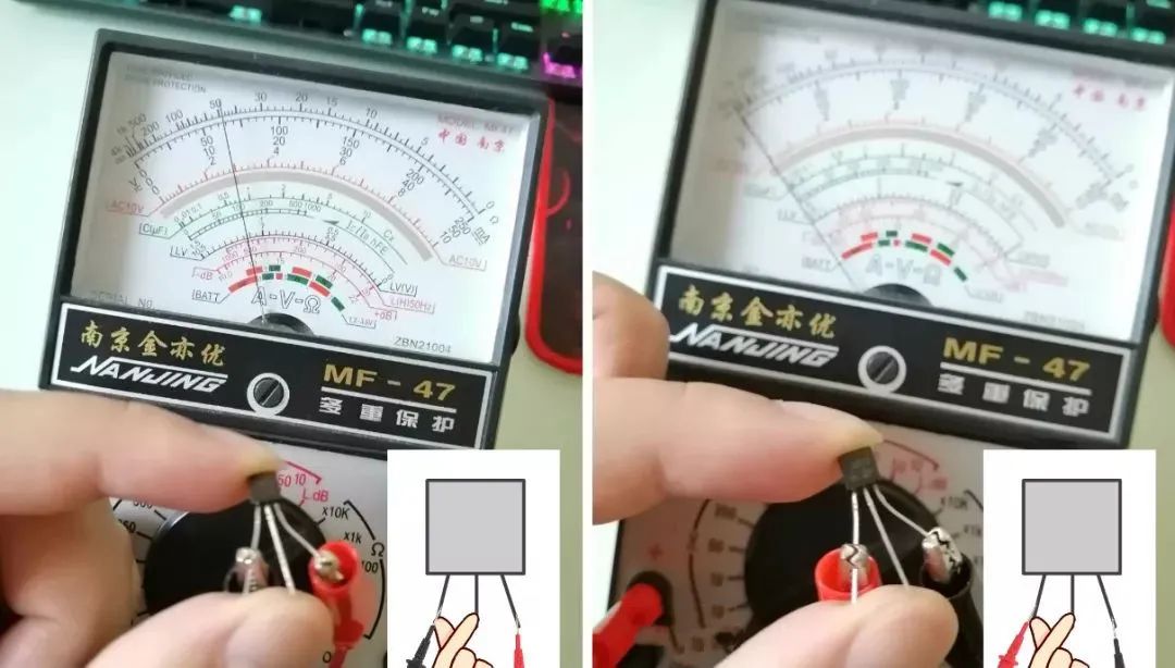
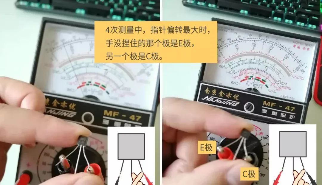
After identifying the B terminal, you can find the C and E terminals. Hold the B terminal and the assumed C terminal, then place the probes on the assumed C and E terminals. If it does not conduct, swap the red and black probes.

2. Measuring with an Analog Multimeter
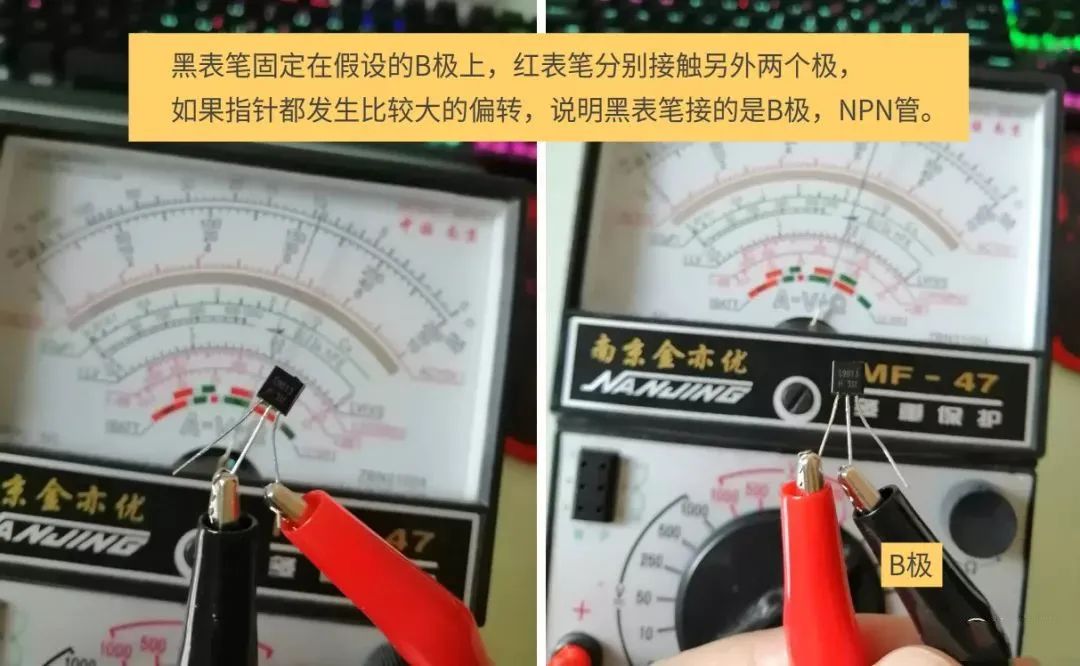
When using an analog multimeter for measurement, the “Rx10K” resistance range is used. If measuring with other resistance ranges, the needle may not deflect enough to be easily observed.
When using the resistance range of an analog multimeter, the red probe corresponds to the negative terminal of the battery, and the black probe corresponds to the positive terminal, meaning current flows from the black probe, which differs from the digital multimeter.
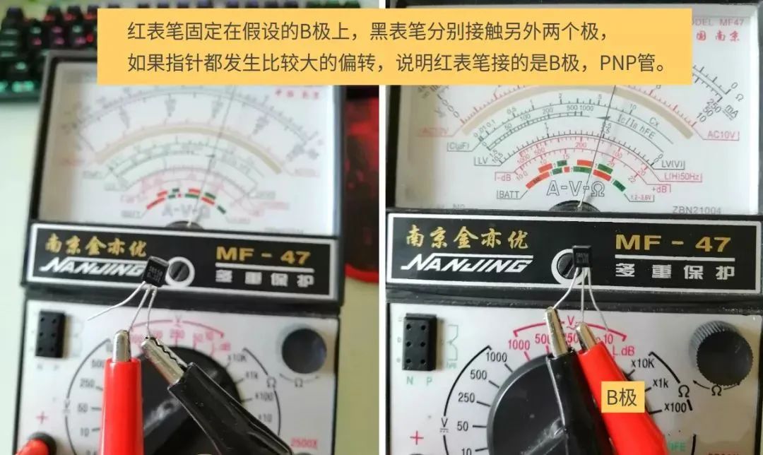
During measurement, we can first assume one of the terminals is the B terminal, then fix one probe on the assumed B terminal and touch the other two leads with the other probe.

★ Disclaimer: Some content is compiled from the internet, and copyright belongs to the author. For copyright issues, please contact us, and we will delete it as soon as possible.
Click the above ↗[●●●] to send to friends or share to Moments
Click Read Original to get more! If you like this article, give it a thumbs up below!
