Click on the above “ Tech Training ” and select “Pin to Top Official Account”
Over 140,000 industrial control professionals follow this WeChat platform: Technical sharing, learning exchange, industrial control videos
A multimeter is also known as a multimeter, three-in-one meter, or multifunction meter. It is a multifunctional and multi-range measuring instrument. Generally, a multimeter can measure DC current, DC voltage, AC voltage, resistance, and audio levels. Some can also measure AC current, capacitance, inductance, and certain parameters of semiconductors (such as β).
1

There are many types of multimeters with various shapes, but the basic structure and usage methods are the same. The main components on the multimeter’s panel include the meter head and the selection switch. There are also a zero adjustment knob for the ohm range and probe sockets. Below are the functions of each part:
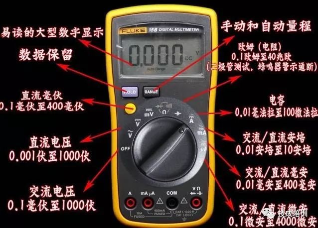
(1) Meter Head
The meter head of the multimeter is a sensitive ammeter.
The symbols A, V, and Ω indicate that this meter can measure current, voltage, and resistance.
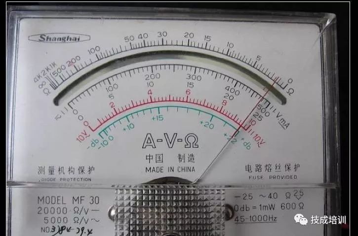
The dial has several scale lines, with the rightmost labeled “Ω” for the resistance scale, where the right end is zero and the left end is ∞, and the scale values are unevenly distributed. The symbol “-” or “DC” indicates direct current, while “~” or “AC” indicates alternating current. The “~” symbol indicates a scale shared by both AC and DC.
Below the scale lines are several rows of numbers corresponding to the different positions of the selection switch.
The meter head also has a mechanical zero adjustment knob to calibrate the pointer to zero on the left end.
(2) Selection Switch
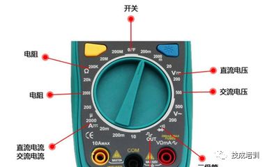
The selection switch of the multimeter is a multi-position rotary switch.
It is used to select measurement items and ranges.
Common measurement items for a multimeter include: “mA” for DC current, “V” for DC voltage, “V” for AC voltage, and “Ω” for resistance. Each measurement item is further divided into several different ranges for selection.
(3) Probes and Probe Sockets
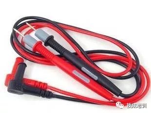
The probes come in red and black; when using, the red probe should be inserted into the socket marked with “+” and the black probe into the socket marked with “-”.
2

Note:
(1) Before using the multimeter, you should:
1. Place the multimeter horizontally.
2. Check if the pointer is at the zero position on the left end of the dial. If it is off, gently turn the mechanical zero adjustment knob on the meter head with a small screwdriver to make the pointer point to zero.
3. Insert the probes into the probe sockets as required above.
4. Rotate the selection switch to the corresponding item and range, and you can use it.
(2) After using the multimeter, you should:
1. Remove the probes.
2. Rotate the selection switch to the “OFF” position; if there is no such position, rotate it to the maximum AC voltage range, such as the “1000V” range.
3. If not used for a long time, remove the battery from the meter to prevent battery electrolyte leakage from corroding the internal circuit.
3

Measuring DC Voltage Steps:
1. Select Range The DC voltage range on the multimeter is marked with “V” and has five ranges: 2.5V, 10V, 50V, 250V, and 500V. Select the range based on the voltage of the power supply in the circuit. Since the power supply voltage in the circuit is only 3V, the 10V range is selected. If the voltage size is unclear, first measure with the highest voltage range, then gradually switch to lower voltage ranges. Connect the output terminals (positive and negative) of the temperature probe to the “μA, Id, ℃” and “COM” sockets of the multimeter.
2. Measurement Method
The multimeter should be connected in parallel with the circuit being measured. The red probe should connect to the positive terminal of the power supply and the black probe to the negative terminal. Place the function switch in the temperature measurement range for the object being measured. Connect the output terminals (positive and negative) of the temperature probe to the “μA, Id, ℃” and “COM” sockets of the multimeter.
When measuring a certain electrical quantity, do not change the range while measuring, especially when measuring high voltages or large currents, as this may damage the multimeter. If a range change is necessary, disconnect the probes first, change the range, and then measure.
3. Correct Reading
Carefully observe the dial; the second scale line is for the DC voltage range. When using the 10V range, you can directly read the measured voltage value from the third row of numbers below the scale line. Note that when reading, your line of sight should be directly aligned with the pointer. Read the measurement result from the LCD display.
Recommended Reading:
Multimeter User Manual Essential for Electricians!
Digital Multimeter Ohm Range Usage and Measurement Methods
Practical Sharing | Multimeter Troubleshooting of Lighting Circuits
Step-by-Step Guide to Using a Multimeter, Share Now!
Quickly Understand Digital Multimeter Testing for Voltage, Current, and Resistance
Share with Friends, Let’s Take a Look
Click Read the Original Text to Learn about Electricians, PLCs, Variable Frequency Servos, CNC Robots, and More