When testing a signal with an output impedance of 50Ω using a Pico oscilloscope, a 50Ω to 1MΩ direct terminal is required.
Recently, during an on-site test with a client, I found that the waveform oscillated severely, as shown in Figure 1 (red box), making it impossible to conduct accurate data analysis.
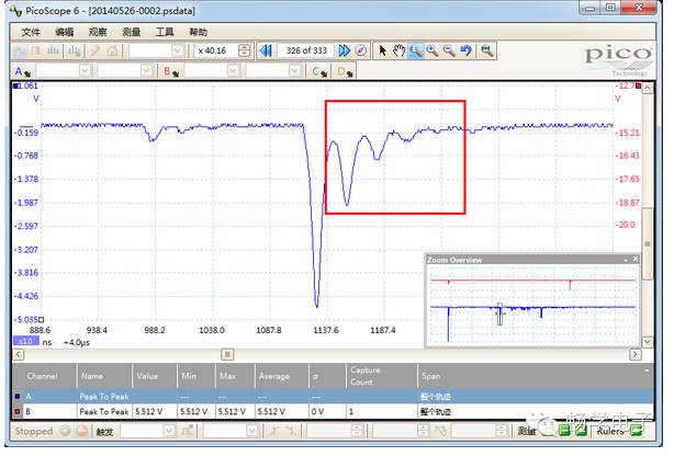
Figure 1 Severe waveform oscillation
After analysis, it was found that the signal output impedance was 50Ω, while the oscilloscope’s input impedance was 1MΩ, causing waveform oscillation due to impedance mismatch. After adding a 50Ω to 1MΩ direct terminal, the measured waveform showed no oscillation, as shown in Figure 2.
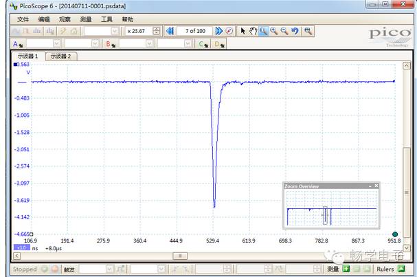
It was also understood that when the input impedance is 50Ω, the maximum measurable voltage is 5VRMS, meaning that the oscilloscope’s measurement range must be below ±5V; otherwise, the impedance matching circuit may be damaged.