
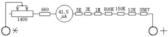
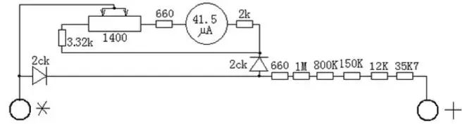
The diagram helps to understand the internal principles of the multimeter, why it can measure high voltage, and under what circumstances measuring high voltage could damage the meter. The diagram can be used to repair multimeters and to create multimeters.
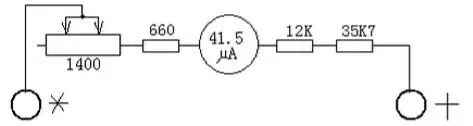
1. DC 2.5V. Set the left switch to 2.5V and the right switch to the V range. + terminal — right switch — V range, 35 kΩ resistor — 12k resistor — left switch — right side of the meter, meter — 660Ω resistor — 1400 potentiometer — common terminal.
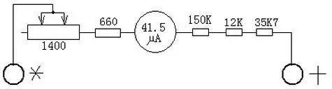
2. DC 10V. Set the left switch to 10V and the right switch to the V range. + terminal — right switch — V range, 35 kΩ resistor — 12k resistor — 150k resistor — left switch — right side of the meter, meter — 660Ω resistor — 1400 potentiometer — common terminal.
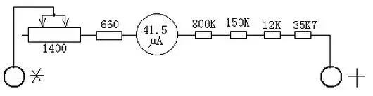
3. DC 50V. Set the left switch to 50V and the right switch to the V range. + terminal — right switch — V range, 35 kΩ resistor — 12k resistor — 150k resistor — 800k resistor — left switch — right side of the meter, meter — 660Ω resistor — 1400 potentiometer — common terminal.
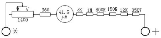
4. DC 250V. Set the left switch to 250V and the right switch to the V range. + terminal — right switch — V range, 35 kΩ resistor — 12k resistor — 150k resistor — 800k resistor — 3k + 1M resistor — left switch — right side of the meter, meter — 660Ω resistor — 1400 potentiometer — common terminal.
5. DC 500V. Set the left switch to 500V and the right switch to the V range. + terminal — right switch — V range, 35 kΩ resistor — 12k resistor — 150k resistor — 800k resistor — 3k + 1M resistor — 5k resistor — left switch — right side of the meter, meter — 660Ω resistor — 1400 potentiometer — common terminal.
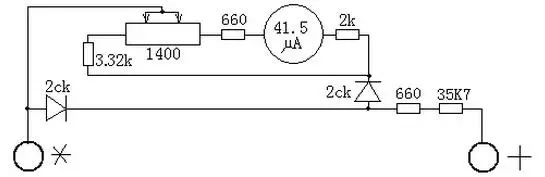
6. AC 10V. Set the left switch to AC 10V and the right switch to the V range. + terminal — right switch — V range, 35 kΩ resistor, left switch position 5 — 660Ω resistor, divided into two paths, one path (positive half wave) — right diode — 2k resistor — left switch position 4 — right end of the meter, meter — 660Ω resistor — 1400 potentiometer — common terminal; the other path (negative half wave) — left diode — common terminal.
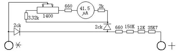
7. AC 50V. Set the left switch to AC 50V and the right switch to the V range. + terminal — right switch — V range, 35 kΩ resistor, 12k, 150k resistors, left switch position 5 — 660Ω resistor, divided into two paths, one path (positive half wave) — right diode — 2k resistor — left switch position 4 — right end of the meter, meter — 660Ω resistor — 1400 potentiometer — common terminal; the other path (negative half wave) — left diode — common terminal.
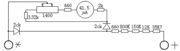
8. AC 250V. Set the left switch to AC 250V and the right switch to the V range. + terminal — right switch — V range, 35 kΩ resistor, 12k, 150k, 800k resistors, left switch position 5 — 660Ω resistor, divided into two paths, one path (positive half wave) — right diode — 2k resistor — left switch position 4 — right end of the meter, meter — 660Ω resistor — 1400 potentiometer — common terminal; the other path (negative half wave) — left diode — common terminal.
9. AC 500V. Set the left switch to AC 500V and the right switch to the V range. + terminal — right switch — V range, 35 kΩ resistor, 12k, 150k, 800k, 1M resistors, left switch position 5 — 660Ω resistor, divided into two paths, one path (positive half wave) — right diode — 2k resistor — left switch position 4 — right end of the meter, meter — 660Ω resistor — 1400 potentiometer — common terminal; the other path (negative half wave) — left diode — common terminal.
(To be continued)
For more information on equipment management activities, please follow “Equipment Management Training”