Background Knowledge
The 4×4 matrix keypad is a commonly used input device in embedded systems, consisting of 16 keys arranged in 4 rows and 4 columns (a total of 16 keys). Compared to individual keys, it significantly saves IO port resources (only 8 IO ports are needed to control 16 keys, while individual keys require 16). It is widely used in human-computer interaction scenarios with controllers such as Arduino, 51 microcontrollers, and STM32 (e.g., password input, function selection, parameter settings, etc.).
1. Hardware Structure
-
Key Layout: The 16 keys are located at the intersection of 4 rows (Row) and 4 columns (Column), with each key corresponding to a unique “row-column” coordinate (e.g., Row 0 Column 0, Row 1 Column 3, etc.).
-
IO Port Connection: 4 row pins (Row Pins) and 4 column pins (Column Pins) are connected to the IO ports of the controller. The keys essentially act as mechanical switches between the “row” and “column” (closed when pressed, open when released).
2. Scanning Principle
The controller identifies the pressed keys through a “row scanning + column detection” method, with the core logic as follows:
-
Row Drive: Set a specific row pin to low (pull down) while setting other row pins to high (pull up);
-
Column Detection: While pulling down a specific row, read the level status of all column pins;
-
Key Recognition: If a column pin detects a low level, it indicates that the key at the intersection of the “currently pulled down row” and the “detected low column” has been pressed;
-
Loop Scanning: Repeat the above steps to quickly scan the 4 rows, achieving the effect of “real-time detection of all keys” (scanning frequency is usually ≥10Hz to avoid missing key presses).
The functions of the 8 pins of the matrix keypad are as follows: (with the keypad facing up, from left to right, they represent pins 1 to 8)
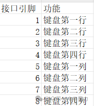
Thus, the current actual key value can be determined by the coordinates represented by the electrical signals when the keys are pressed.
1. Electronic Components Used in the Experiment
1 Arduino board, 1 USB data download cable, several Dupont wires
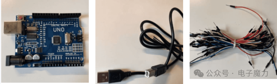
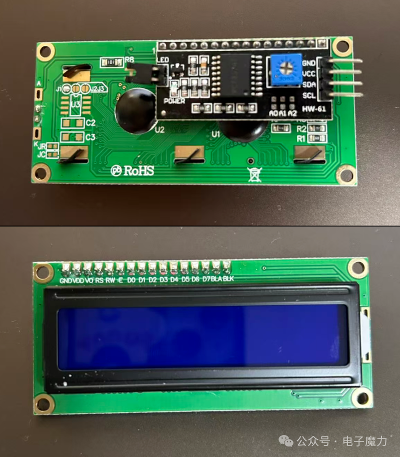
1 LCD1602 IIC LCD display (with integrated driver circuit)
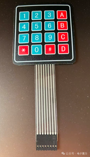
1 4×4 matrix keypad (with a total of 8 pins, from left to right, pins 1 to 8, pins 1 to 4 control the rows of the keypad, and pins 5 to 8 control the columns)
2. Experimental Steps
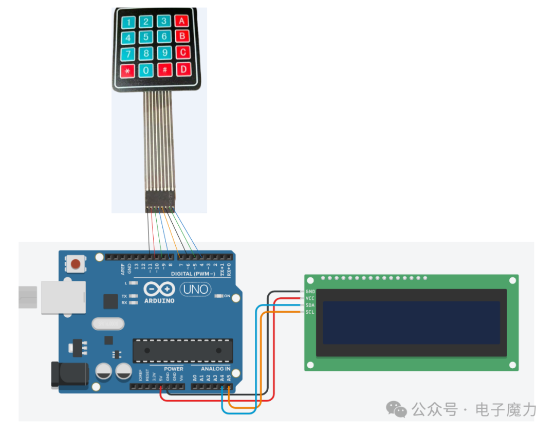
The wiring method is shown in the figure below
Wiring for LCD1602:
-
GND → Arduino GND
-
VCC → Arduino 5V
-
SDA → A4
-
SCL → A5
Wiring for the matrix keypad: (from left to right, pins 1 to 8)
-
Pin 1 → Arduino Pin 11
-
Pin 2 → Arduino Pin 10
-
Pin 3 → Arduino Pin 9
-
Pin 4 → Arduino Pin 8
-
Pin 5 → Arduino Pin 7
-
Pin 6 → Arduino Pin 6
-
Pin 7 → Arduino Pin 5
-
Pin 8 → Arduino Pin 4
3. Program Code
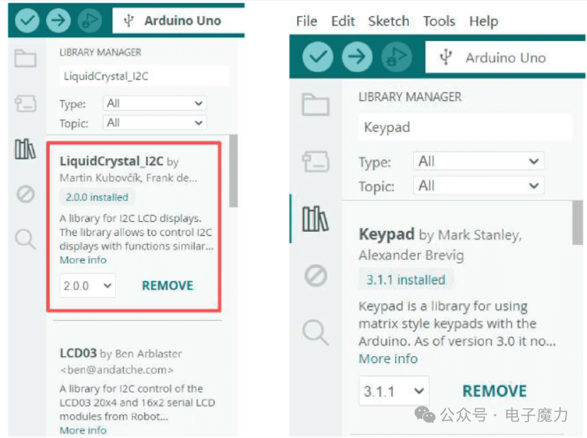
The experiment code requires the inclusion of the LiquidCrystal_I2C.h third-party library to drive the LCD1602 display; the Keypad.h library is included to control the matrix keypad. Search for and install these two libraries in the IDE, ensuring that any dependent libraries are also installed.
Program Code:
#include <LiquidCrystal_I2C.h>  // Import LCD1602 I2C driver library
#include <Wire.h>               // Import I2C communication library (required for LCD1602 I2C mode)
#include <Keypad.h>             // Import matrix keypad library
// -------------------------- Hardware Parameter Configuration --------------------------
const uint8_t LCD_ADDR = 0x27;  // I2C device address for LCD1602 (common values are 0x27 or 0x3F)
const uint8_t LCD_COLS = 16;    // Number of columns for LCD1602 (16 columns)
const uint8_t LCD_ROWS = 2;     // Number of rows for LCD1602 (2 rows)
// Matrix keypad configuration (4 rows and 4 columns)
const byte KEYPAD_ROWS = 4;  // Number of rows in the keypad
const byte KEYPAD_COLS = 4;  // Number of columns in the keypad
// Key mapping table (corresponding to actual key positions)
char keyMap[KEYPAD_ROWS][KEYPAD_COLS] = {  { '1', '2', '3', 'A' },  { '4', '5', '6', 'B' },  { '7', '8', '9', 'C' },  { '*', '0', '#', 'D' }};
// Row pins for the keypad (connected to Arduino digital pins)
byte rowPins[KEYPAD_ROWS] = { 11, 10, 9, 8 };
// Column pins for the keypad (connected to Arduino digital pins)
byte colPins[KEYPAD_COLS] = { 7, 6, 5, 4 };
// -------------------------- Global Objects and Variables --------------------------
LiquidCrystal_I2C lcd(LCD_ADDR, LCD_COLS, LCD_ROWS);  // Instantiate LCD1602 object
Keypad customKeypad = Keypad(                         // Instantiate matrix keypad object
  makeKeymap(keyMap),                                 // Key mapping table
  rowPins,                                            // Row pin array
  colPins,                                            // Column pin array
  KEYPAD_ROWS,                                        // Number of rows
  KEYPAD_COLS                                         // Number of columns);
uint8_t inputCount = 0;  // Record the number of key inputs (used to control LCD display position)
// -------------------------- Initialization Function --------------------------
void setup() {  lcd.init();               // Initialize LCD1602  lcd.backlight();          // Turn on LCD backlight  lcd.setCursor(0, 0);      // Set initial cursor position (column 0, row 0)  lcd.print("loading...");  // Welcome message on startup  delay(1500);              // Display prompt for 1.5 seconds  lcd.clear();              // Clear screen to prepare for input}
// -------------------------- Main Loop Function --------------------------
void loop() {  char pressedKey = customKeypad.getKey();  // Get key input (returns 0 if no key is pressed)  // Detect valid key input  if (pressedKey != 0) {    // Calculate cursor position based on input count    // Row 0: Input count 0-15 (corresponding to columns 0-15)    // Row 1: Input count 16-31 (corresponding to columns 0-15)    uint8_t col = inputCount % LCD_COLS;  // Calculate column position (modulo 16)    uint8_t row = inputCount / LCD_COLS;  // Calculate row position (integer division by 16)    lcd.setCursor(col, row);  // Set cursor to current input position    lcd.print(pressedKey);    // Display key character at current position    inputCount++;  // Increment input count    // When 32 characters are input (2 rows × 16 columns), clear screen and reset    if (inputCount >= LCD_COLS * LCD_ROWS) {      delay(500);      // Delay 500ms to allow the last character to display completely      lcd.clear();     // Clear screen      inputCount = 0;  // Reset input count    }  }}
4. Experimental Results
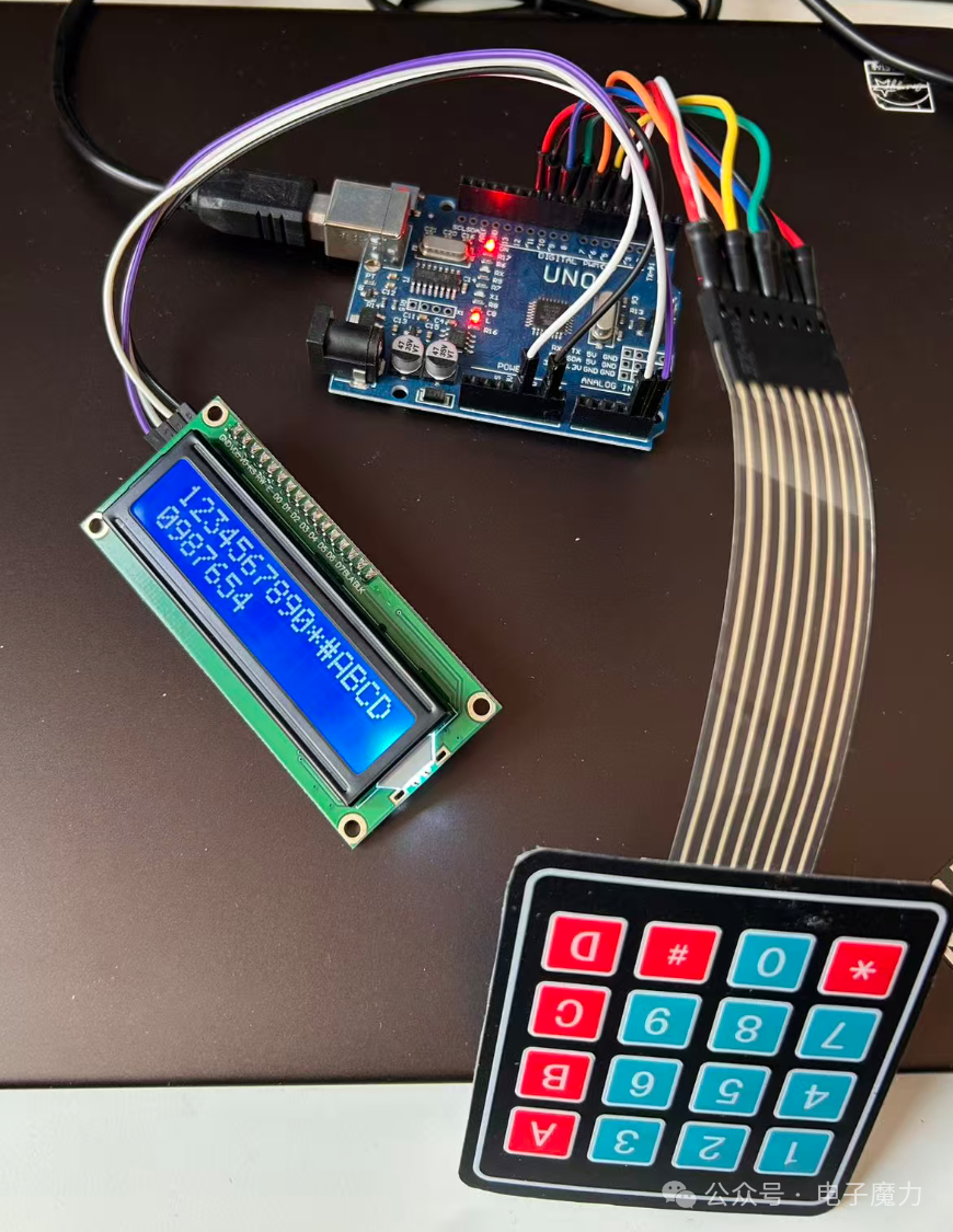
After successfully uploading the program, the LCD1602 screen will light up and display a loading state. After 1.5 seconds, key input can be performed. When a single line exceeds 16 characters, it will automatically wrap to the next line, and when exceeding two lines, the screen will automatically clear.
Wiring Physical Diagram:
Experimental Video:
The code in this article has been uploaded to Gitee, see the link: https://gitee.com/webxiaohua/arduino-learn/tree/master/28_ju_zhen_jian_pan