In the field of embedded systems, microcontrollers (MCUs) serve as core control units and are widely used in home appliances, industrial control, and the Internet of Things (IoT). However, traditional microcontroller development has a high barrier to entry and relatively fixed functions, limiting its potential in the era of intelligence. With the rapid development of artificial intelligence (AI) technology, the deep integration of AI and microcontrollers is breaking this deadlock (Methods and Steps for AI Empowering Microcontroller Development). This article will focus on two typical AI + microcontroller application scenarios: a voice-controlled home appliance system based on the LD3320 voice module and an image recognition smart trash can system based on the OV7670 camera, showcasing how AI injects innovative vitality into traditional microcontrollers.
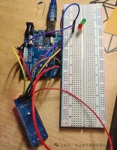
Image showing the connection between the microcontroller development board and the breadboard, demonstrating the basic environment for hardware circuit construction.
1.1 Technical Analysis of the LD3320 Voice Module
The LD3320 is a high-performance, low-power voice recognition chip developed by Sunplus Technology, specifically designed for voice recognition applications and widely used in smart homes, security systems, and smart toys (Detailed Explanation of the LD3320 Voice Recognition Chip). This module has the following key features:
- Hardware Interface: Uses SPI communication protocol with only 4 connections (VCC, GND, SCK, SDI), saving chip pins and PCB space.
- Recognition Capability: Supports 50 recognition entries, each can be set to standard Mandarin Chinese pinyin.
- Operating Parameters: Serial communication baud rate of 9600bps, 8 data bits, requires an external stable 5V power supply.
- The module pin definitions are as follows:
1. VCC – Power positive (5V) 2. GND – Power negative 3. TXD – Serial data output (connect to microcontroller RX) 4. RXD – Serial data input (connect to microcontroller TX) 5. BUSY – Busy indicator (high level working/low level idle) 6. RESET – Reset input (high level reset) 7. SPK+/- – Voice output terminal (connect to speaker)
1.2 System Hardware Setup
The core of the voice-controlled home appliance system is the connection between the LD3320 module and the microcontroller (such as STM32 or Arduino). Below is a typical SPI interface connection method (Learning SPI + LD3320 Voice Chip):
// Example of STM32 SPI2 connection with LD3320 hspi2.Instance = SPI2; hspi2.Init.Mode = SPI_MODE_MASTER; hspi2.Init.Direction = SPI_DIRECTION_2LINES; hspi2.Init.DataSize = SPI_DATASIZE_8BIT; hspi2.Init.CLKPolarity = SPI_POLARITY_HIGH; hspi2.Init.CLKPhase = SPI_PHASE_1EDGE; hspi2.Init.NSS = SPI_NSS_SOFT; hspi2.Init.BaudRatePrescaler = SPI_BAUDRATEPRESCALER_2; hspi2.Init.FirstBit = SPI_FIRSTBIT_MSB;
1.3 Software Implementation and Code Analysis
The voice recognition process includes three main steps: initialization, writing the recognition list, and interrupt handling. Below are key code snippets (LD3320 voice recognition module controlling LED and SG90 servo with Arduino UNO):
// Initialize LD3320 void LD3320_Init()
{ // Reset module digitalWrite(RST_PIN, LOW); delay(100); digitalWrite(RST_PIN, HIGH); // SPI initialization SPI.beginTransaction(SPISettings(1000000, MSBFIRST, SPI_MODE0)); // Write recognition list LD3320_WriteReg(0x05, 0x00); // Clear recognition list LD3320_WriteList(“kai deng”, 0x01); // Add “turn on light” command LD3320_WriteList(“guan deng”, 0x02); // Add “turn off light” command } // Interrupt handler void interruptHandler()
{ uint8_t result = LD3320_ReadReg(0xC5); // Read recognition result switch(result)
{ case 0x01: digitalWrite(LED_PIN, HIGH); break; // Turn on light case 0x02: digitalWrite(LED_PIN, LOW); break; // Turn off light }}
Sometimes when writing technical articles, I experience a mental block, and I often like to snack on something. I recommend raisins to everyone.
If you need, you can buy them yourself; they are really delicious:

Continuing to write the unfinished article…
Part Two: Image Recognition Smart Trash Can System
2.1 Technical Features of the OV7670 Camera Module
The OV7670 is a 1/6 inch CMOS VGA image sensor produced by OmniVision, with the following characteristics (Introduction to the OV7670 Camera Module):
- Resolution Support: Supports a maximum resolution of 640×480 (VGA) at 30 frames per second.
- Data Interface: 8-bit parallel data output, supports SCCB (I2C compatible) control interface.
- Image Processing: Built-in DSP for automatic exposure, white balance, gamma correction, and other functions.
- Output Format: Supports various formats such as RGB565 and YUV.
2.2 Advantages of the OV7670 Module with FIFO
For low-speed microcontrollers, it is recommended to use the OV7670 module with FIFO (AL422B), which solves the speed bottleneck of image acquisition (Guide to OV7670 with FIFO). FIFO acts as a data buffer, allowing the microcontroller to read image data at its own speed. The key operation timing is as follows:
// Pseudocode for FIFO read/write control void CaptureFrame()
{ FIFO_WRST_L(); // Reset FIFO write pointer while(WAIT_VSYNC()); // Wait for frame sync signal FIFO_WEN_H(); // Enable FIFO write while(WAIT_VSYNC()); // Wait for the next frame to start FIFO_WEN_L(); // Disable FIFO write FIFO_RRST_L(); // Reset FIFO read pointer for(int i=0; i<WIDTH*HEIGHT; i++) { FIFO_RCLK_H(); // Generate read clock pixel = FIFO_DATA; // Read pixel data FIFO_RCLK_L(); ProcessPixel(pixel); // Process pixel }}
2.3 Image Recognition Implementation Based on TinyML
To implement image recognition on resource-constrained microcontrollers, TinyML technology can be used. TinyMaix is an ultra-lightweight AI inference framework that can run on an Arduino UNO with only 2KB of RAM (…Implementation of Handwritten Digit Recognition Using TinyMaix). Below is a simplified implementation of the waste classification model:
// TinyML model definition tm_model_t model; uint8_t model_buf[1024]; // Model buffer uint8_t input_buf[28*28]; // Input image buffer void setup()
{ // Load pre-trained waste classification model tm_load(model_buf, &model); // Initialize OV7670 OV7670_Init(RGB565, QVGA);} void loop()
{ CaptureImage(input_buf); // Capture image to buffer // Preprocess: scale to 28×28, convert to grayscale Preprocess(input_buf); // Run inference tm_err_t res = tm_run(&model, input_buf); // Control trash can based on recognition result if(res == TM_OK)
{ uint8_t class = tm_get_result(&model); ControlTrashLid(class); // Open the corresponding trash can lid }}
Part Three: System Optimization and Performance Improvement
3.1 Techniques for Optimizing Voice Recognition Accuracy
Practical methods to improve the recognition rate of the LD3320 include (Introduction to LD3320 Voice Recognition Module Pins):
- Environmental Noise Reduction: Add a simple RC filter circuit to the microphone input.
- Command Design: Use wake words with more than 4 characters, such as “Xiao Du Xiao Du”.
- Stable Power Supply: The module has a relatively large working current (about 80mA), requiring independent LDO power supply.
- List Optimization: Set similar-sounding commands to the same number to improve fault tolerance.
3.2 Image Processing Algorithm Optimization
Practical optimization strategies for the OV7670 (OV7670 Learning Notes):
// Optimized image acquisition process void OptimizedCapture() { // 1. Reduce resolution to QQVGA (160×120) OV7670_SetResolution(QQVGA); // 2. Use YUV format to reduce data size OV7670_SetFormat(YUV422); // 3. Focus on the area of interest (ROI) for trash disposal OV7670_SetWindow(50, 30, 60, 60); // 4. Enable automatic exposure to optimize low-light performance SCCB_Write(0x13, 0x07); // Enable AEC/AGC}
3.3 Integration and Interaction of Dual Systems
Integrating voice control with the image recognition system can create a smarter home appliance control system:
void IntegratedSystem() {
if(VoiceCommand == “waste classification”) { ActivateCamera(); DisplayLiveView(); while(!Timeout) { if(DetectHuman()) { CaptureAndClassify(); PlayVoicePrompt(); } } }}
Conclusion: Future Prospects of AI + Microcontrollers
The combination of AI and microcontrollers is bringing embedded development from a professional field to widespread creativity. Through the two typical cases of LD3320 and OV7670, we see how AI technologies such as voice recognition and image processing can be embedded into traditional microcontroller systems. In the future, with the development of RISC-V architecture and AI coprocessors, as well as advancements in algorithm compression technology, AI microcontrollers will become more powerful and widespread (How to Use Microcontrollers Combined with AI Technology for Smart Home Control?).