The concept of 37 types of sensors and actuators is widely circulated on the internet, but in fact, the number of sensor modules compatible with Arduino is certainly more than these 37 types. Given that I have accumulated some sensor and actuator modules, I intend to conduct a series of experiments based on the principle of learning through practice (it is essential to get hands-on). For the purpose of learning and sharing, I will try each experiment one by one, regardless of whether they succeed (the program runs smoothly) or not, and I will document everything—small progress or perplexing issues, hoping to inspire others.
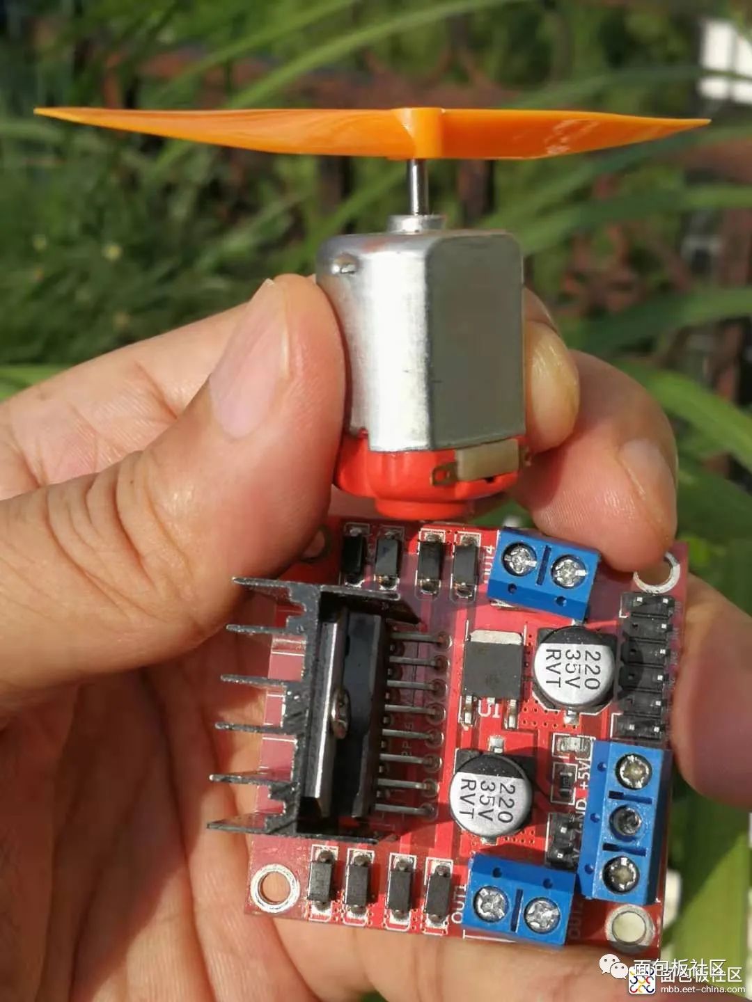
Experiment Ninety-Four: L298N Motor Driver Module for DC Stepper Motor Intelligent Robot Car Module
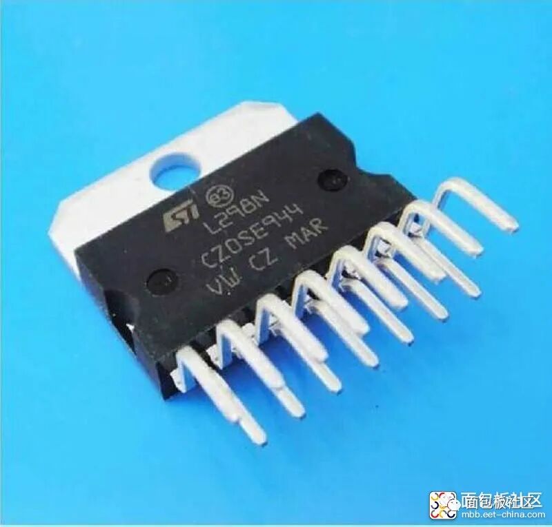
L298N
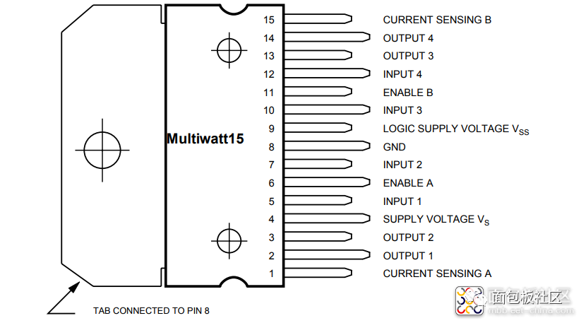
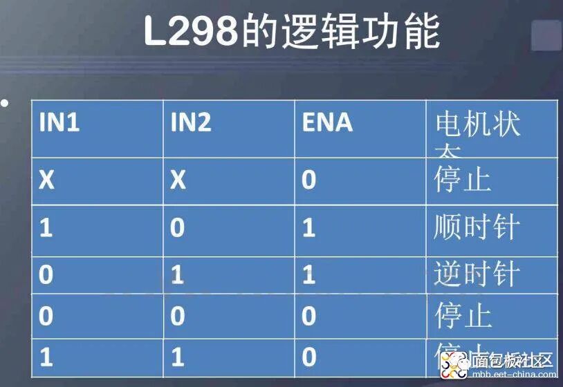
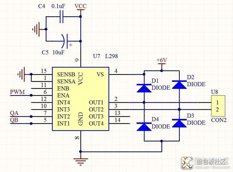
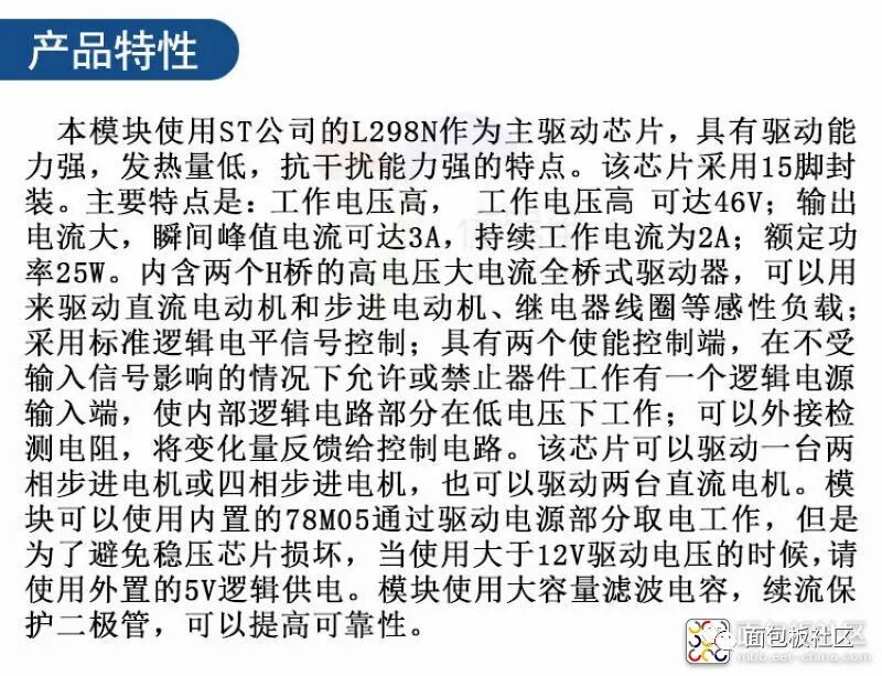
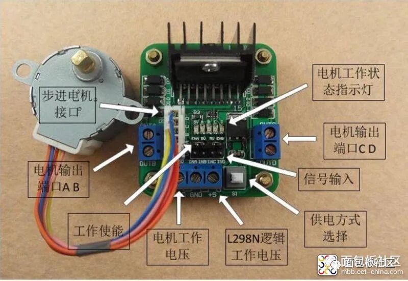
is a dedicated driver integrated circuit, belonging to H-bridge integrated circuits. The difference from L293D is that its output current is increased, and the power is enhanced. Its output current is 2A, with a maximum current of 4A and a maximum operating voltage of 50V. It can drive inductive loads such as high-power DC motors, stepper motors, and solenoid valves, especially since its input can be directly connected to a microcontroller, making it very convenient to control by the microcontroller. When driving a DC motor, it can directly control a stepper motor and achieve forward and reverse rotation of the motor; this function can be realized simply by changing the logic level at the input.The L298N chip can drive two bipolar motors or one four-phase motor, with an output voltage of up to 50V, which can be adjusted directly through the power supply; it can directly use the IO ports of the microcontroller to provide signals; moreover, the circuit is simple and easy to use.The L298N accepts standard TTL logic level signals VSS, where VSS can connect to a voltage of 4.5 to 7V. Pin 4 VS connects to the power supply voltage, and the VS voltage range VIH is +2.5 to 46V. The output current can reach 2A, capable of driving inductive loads. The emitters of the lower transistors at pins 1 and 15 are separately brought out to connect to current sensing resistors, forming current sensing signals. The L298 can drive 2 motors, with OUT1, OUT2 and OUT3, OUT4 connecting to the motors respectively. In this experimental setup, we choose to drive one motor. Pins 5, 7, 10, and 12 connect to input control levels to control the forward and reverse rotation of the motor. EnA and EnB connect to the control enable terminals to control the motor’s stop.

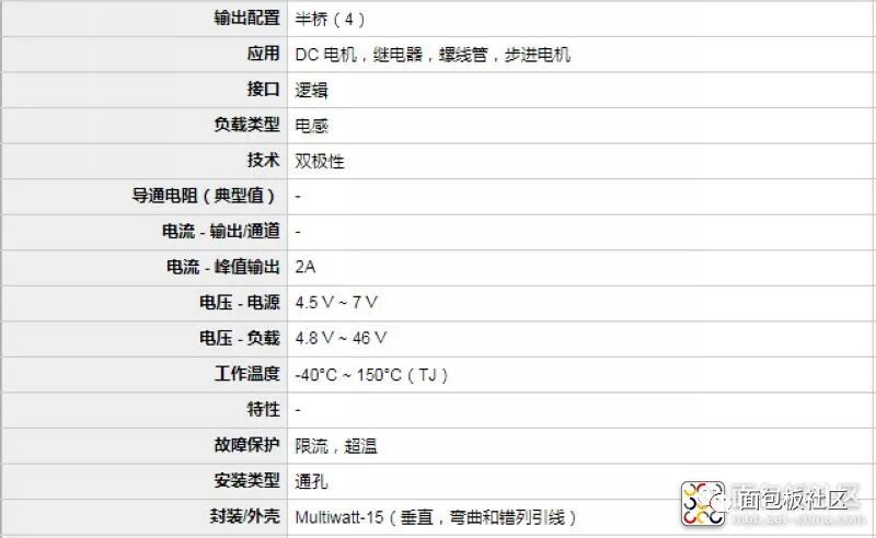

L298N Specifications Type: Half-bridge Input Type: Non-inverting Number of Outputs: 4 Current – Output/Channel: 2A Current – Peak Output: 3A Power Supply Voltage: 4.5V~46V Operating Temperature: -25°C~130°C Mounting Type: Through-hole Package/Enclosure: MulTIwatt-15 (vertical, bent and staggered leads) Supplier Device Package: 15-MulTIwatt Packaging: Tube Device Model: L298N Manufacturer: STMicroelectronics Product Model: MotionMotorControl
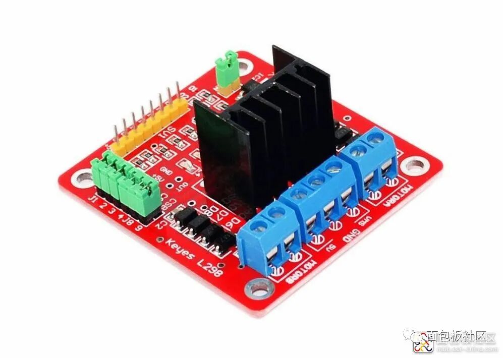
Parameters of the L298N Motor Driver Module1. Driver Chip: L298N Dual H-Bridge DC Motor Driver Chip2. Power Supply Range for Driver Terminals Vs: +5V to +35V; if power is taken from the board, the supply range Vs: +7V to +35V3. Peak Current Io for Driver Section: 2A4. Power Supply Range for Logic Terminals Vss: +5V to +7V (can take +5V from the board)5. Operating Current Range for Logic Section: 0 to 36mA6. Control Signal Input Voltage Range: Low Level: -0.3V ≤ Vin ≤ 1.5V High Level: 2.3V ≤ Vin ≤ Vss7. Enable Signal Input Voltage Range: Low Level: -0.3 ≤ Vin ≤ 1.5V (control signal invalid) High Level: 2.3V ≤ Vin ≤ Vss (control signal valid)8. Maximum Power Consumption: 20W (at temperature T = 75°C)
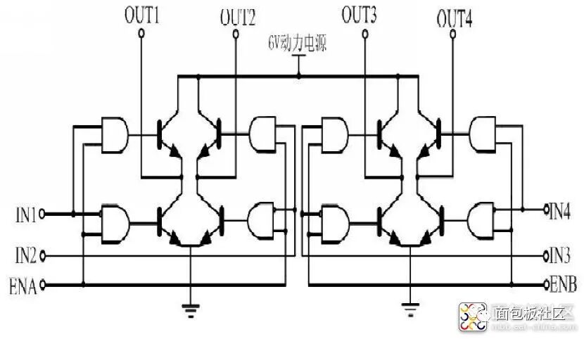
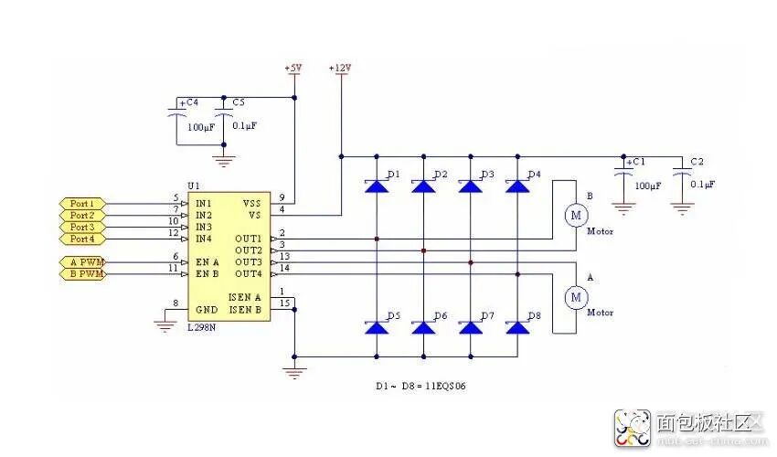
L298N Motor Driver Module Circuit Diagram
Performance Features of the L298N Motor Driver Module: 1: Can achieve motor forward and reverse rotation and speed regulation. 2: Good starting performance, high starting torque. 3: Operating voltage can reach 36V, 4A. 4: Can drive two DC motors simultaneously. 5: Suitable for applications in robot design and intelligent car design.Case One: Using L298N to drive two DC gear motors. Pins A and B can be used for PWM control. If the robot project only requires moving straight, then IN1, IN2 and IN3, IN4 can be connected to high and low levels respectively, and only two ports of the microcontroller need to provide PWM signals to control enable terminals A and B to achieve straight movement, turning, acceleration, and deceleration.Case Two: Using L298 to control a two-phase stepper motor. Connect IN1, IN2 and IN3, IN4 to certain ports of the microcontroller, outputting continuous pulse signals. The signal frequency determines the motor speed. Changing the order of the winding pulse signals can achieve forward and reverse rotation.
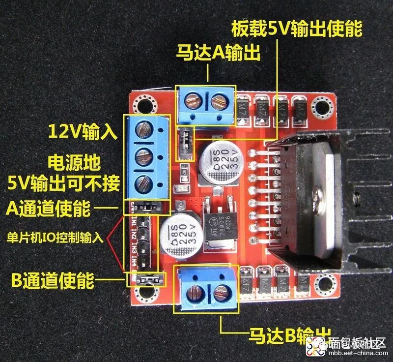
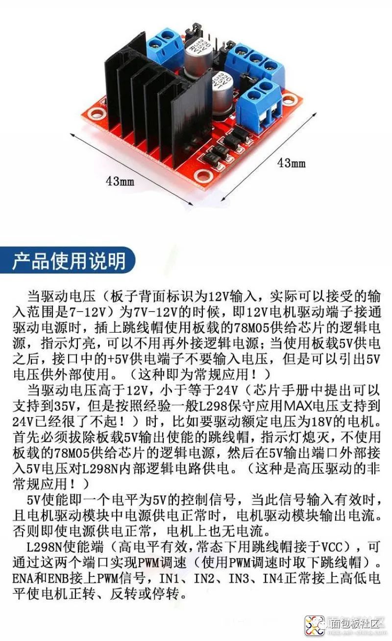
Precautions:1. When your driving voltage (marked as 12V input in the above figure, the actual acceptable input range is 7-12V) is 7V-12V, you can enable the onboard 5V logic power supply. After using the onboard 5V power supply, do not input voltage into the +5V supply in the interface, but you can output 5V voltage for external use. (This is the conventional application!)2. When the driving voltage is above 12V and less than or equal to 24V (the chip manual states it can support up to 35V, but based on experience, generally, a conservative application of 24V is already impressive!), for example, to drive a motor rated at 18V, you must first remove the jumper cap that enables the onboard 5V output. Then connect 5V externally to the 5V output port. The 5V enable is a control signal with a level of 5V. When this signal is valid and the power supply to the motor driver module is normal, the motor driver module will output current. Otherwise, even if the power supply is normal, there will be no current to the motor. The voltage powers the internal logic circuit of the L298N. (This is an unconventional application for high-voltage driving!)3. If the 5V supplied to the L298N is powered by another source (i.e., not shared with the microcontroller’s power supply), then the GND of the microcontroller must be connected to the GND of the module, only then will the logic signals from the microcontroller have a reference ground. This point is very important, please pay attention.
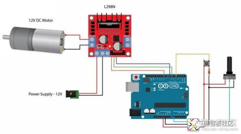
L298N Motor Driver Module Experiment Wiring Diagram

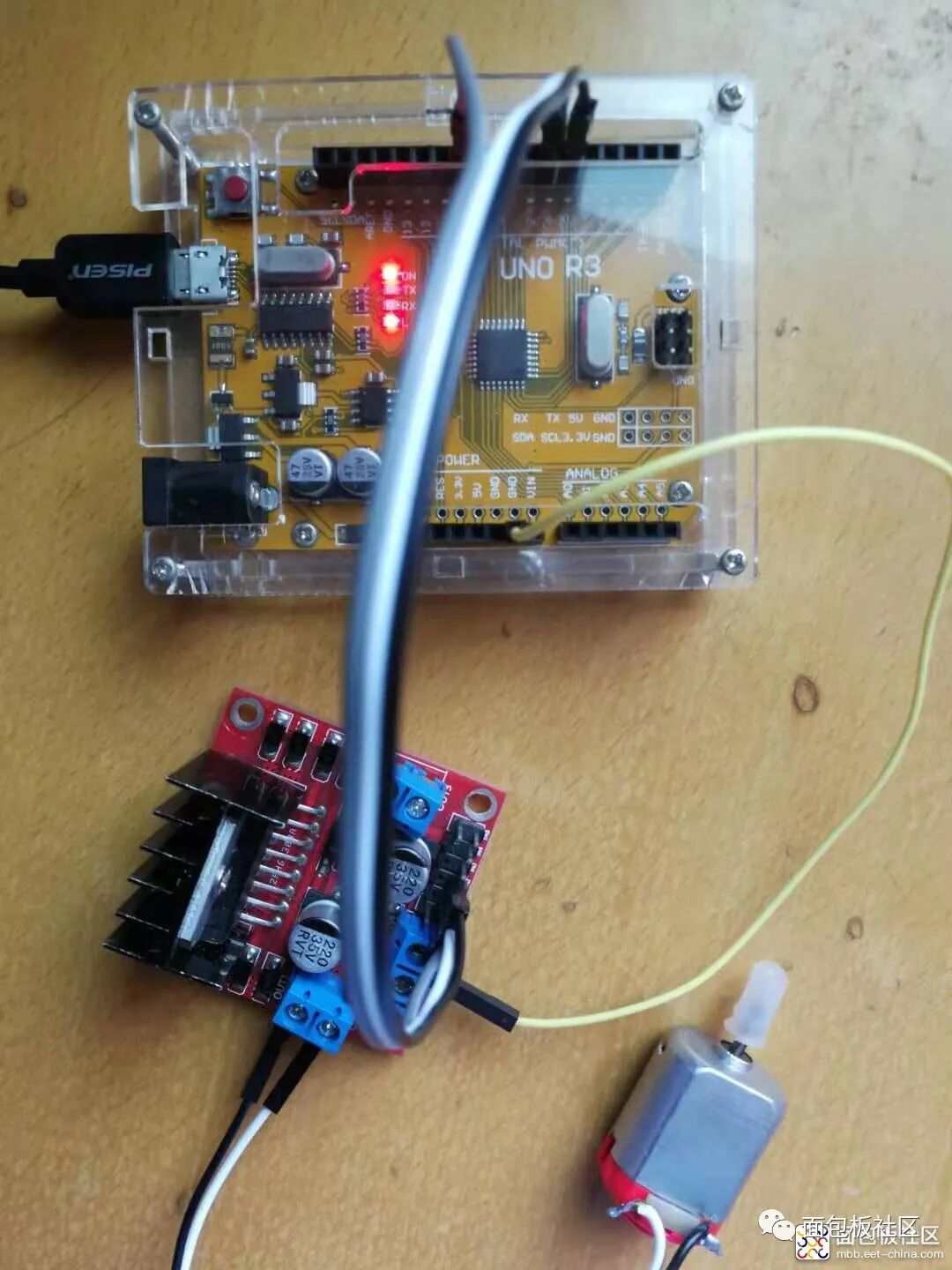
Experiment Open Source Code
/*【Arduino】168 types of sensor module series experiments (data code + simulation programming + graphical programming) Experiment Ninety-Four: L298N Motor Driver Module for DC Stepper Motor Intelligent Robot Car Module Project One: Use analogWrite in Arduino to generate PWM waves. Here, the input values for analogWrite can be 0-255. Of course, the motor will not turn below a certain voltage, so you can change the values to test. The disadvantage of this method is that the PWM frequency cannot be modified.*/int input1 = 5; // Define pin 5 of Uno to output to input1int input2 = 6; // Define pin 6 of Uno to output to input2int enA = 10; // Define pin 10 of Uno to output to enable Avoid setup() {pinMode(input1,OUTPUT);pinMode(input2,OUTPUT);pinMode(enA,OUTPUT);}void loop() {digitalWrite(input1,HIGH); // Set high leveldigitalWrite(input2,LOW); // Set low levelanalogWrite(enA,200);}Experiment Scene Diagram
Experiment Open Source Simulation Programming (Linkboy V4.62)
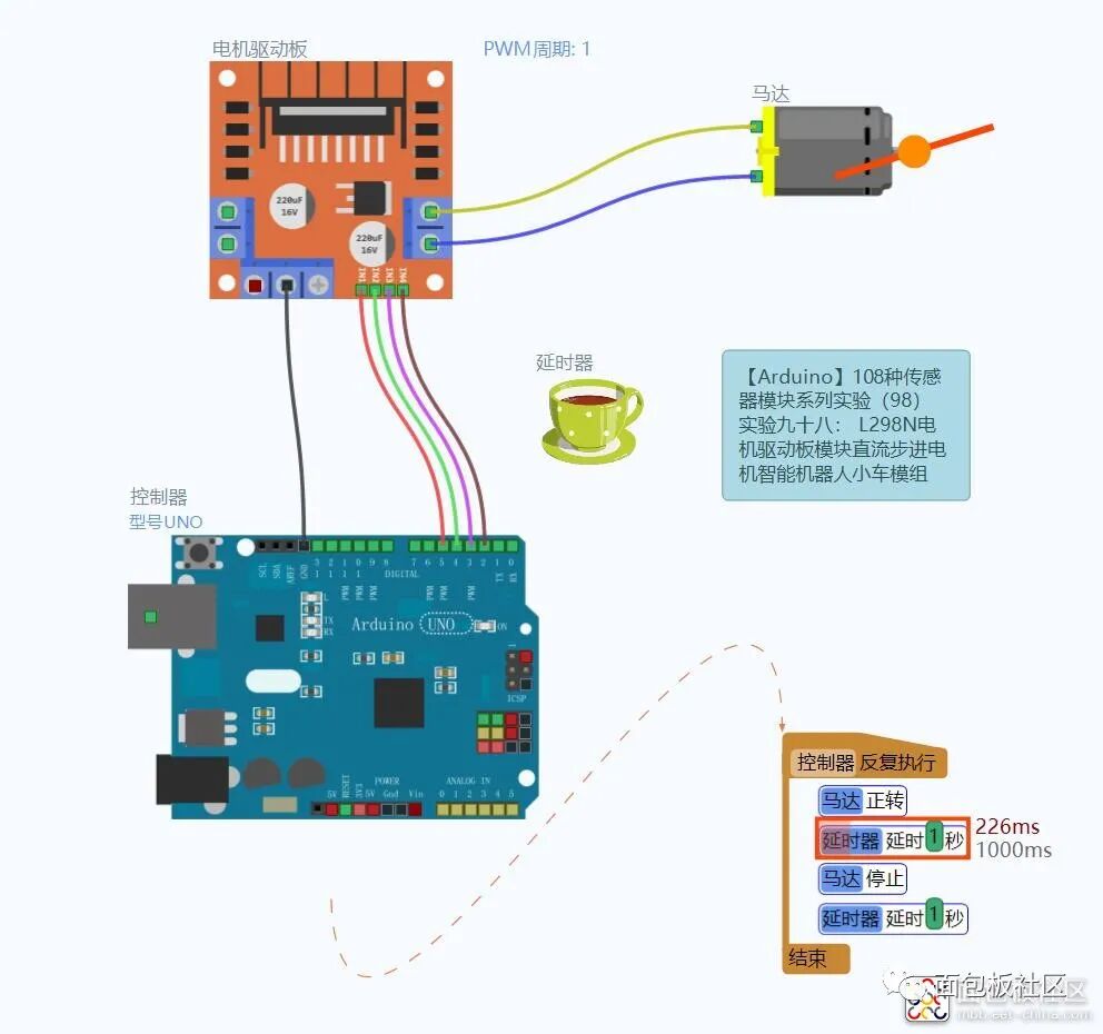
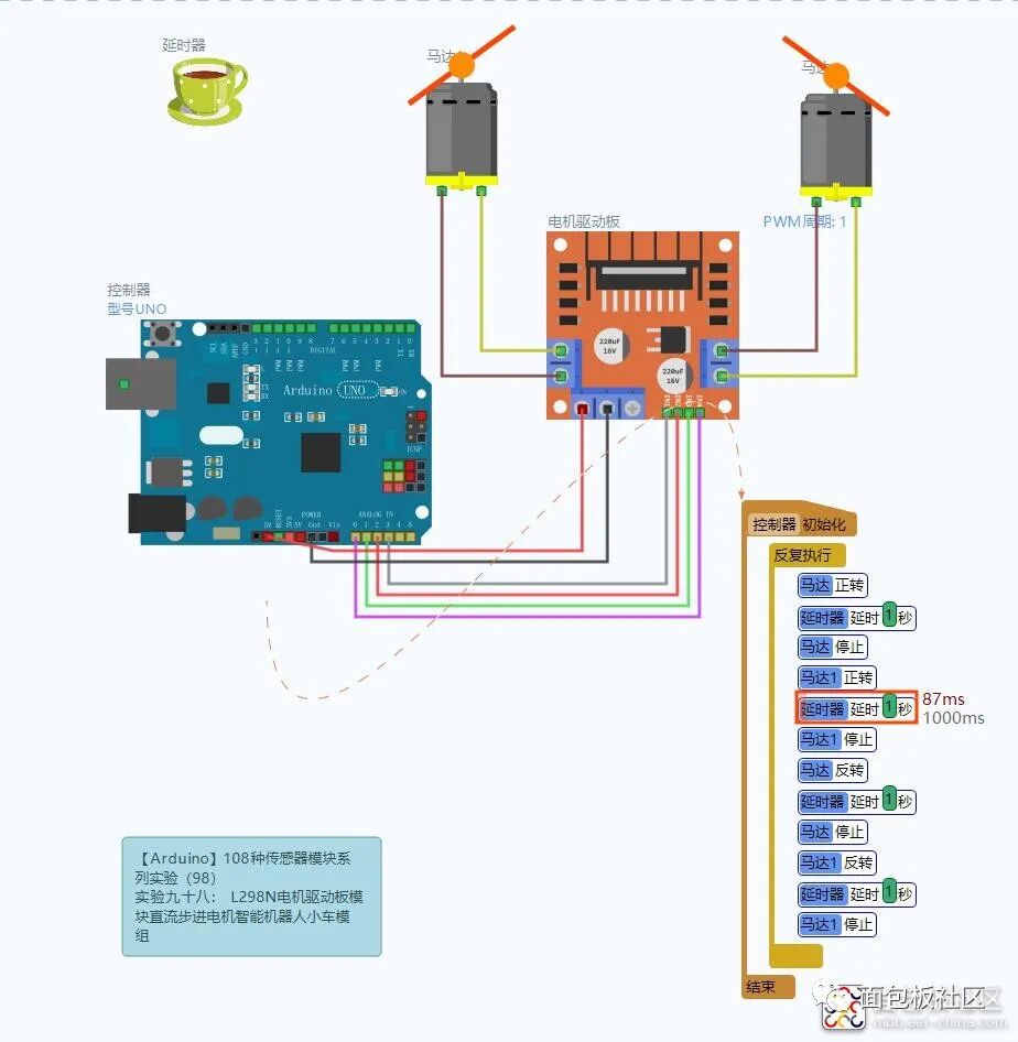

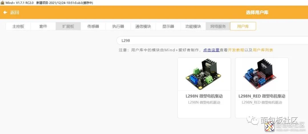
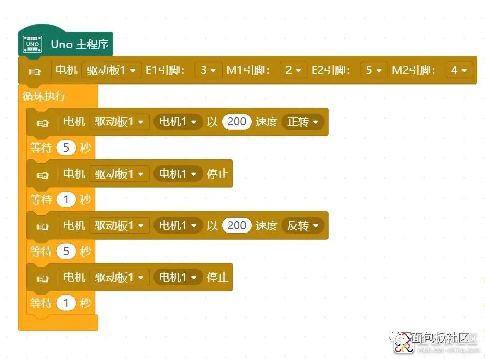
Experiment Open Source Graphical Programming (Mind+, Mixly, Learn by Doing)
Open Mind+, search the user library “L298”
Welcome to follow the EET official community
Learn electronics every day
▼