1. ECC
MIPI CSI-2 uses a 24-bit ECC scheme. Inputting 24bit data, ECC encoding is performed to obtain an 8bit ECC result.
Note: The 7th and 6th bits of the ECC byte must be 0.
Data mapping relationship:
Data identifier in the packet header DI[7:0] → corresponds to ECC input D[7:0]
Low byte of word count in the packet header WC[7:0] → corresponds to ECC input D[15:8]
High byte of word count in the packet header WC[15:8] → corresponds to ECC input D[23:16]
The following figure shows an ECC calculation example, demonstrating the data mapping relationship: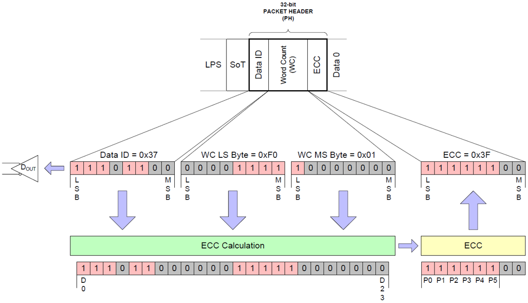 Figure.1 24-bit ECC Generation Example1.1 Hamming Code
Using Hamming Code for ECC calculation.
Hamming Code (Hamming Code) is a coding technique used for error detection and correction, which can automatically correct1bit errors and detect 2bit and above errors.
Encoding rules: In Hamming Code, the number of required parity bits (Parity Bits) follows the rule as shown below: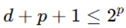
Where, d represents the number of data bits, p represents the number of parity bits.
The calculated parity bits are appended to the data, resulting in what is called a Hamming codeword, with a total length of c=d+p, and the codeword can be represented as (c, d).
1.2 Hamming-Modified Code
Hamming code corrects 1bit errors or detects 2bit errors through parity checking (Parity), but it cannot perform both operations simultaneously. Therefore, we need to add an additional 1 parity bit.
This coding scheme’s 6bit syndrome can correct 64bit sequences within the first 24bit.
To compactly encode parity and efficiently decode the syndrome, a special matrix is used:
(1) Each cell in the matrix represents a syndrome;
(2 The first 24 cells (orange row) only use the first 3bit or 5bit to construct the syndrome;
(3 The syndrome uses the most significant bit (MSB Left-Aligned).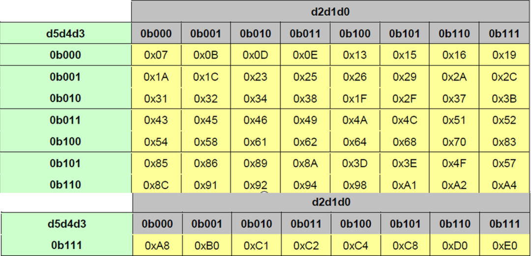
1.3 ECC Generation on TX side
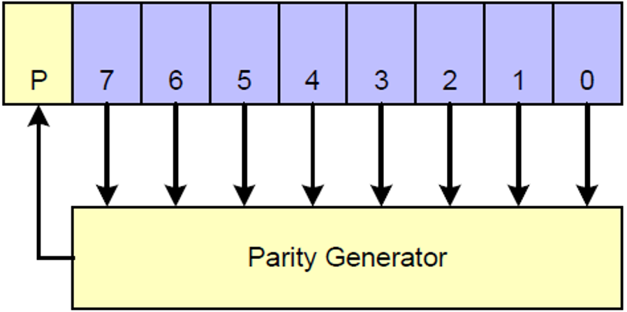
Figure 2. 64-bit ECC Generation on TX Side
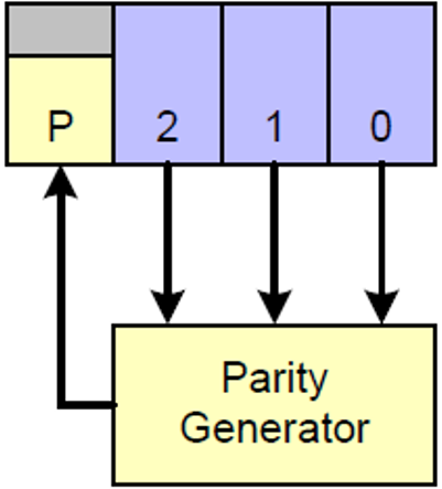
Figure 3. 24-bit ECC Generation on TX Side
1.4 Applying ECC on RX side
(1) The receiver recalculates the ECC for the received data packet;
(2) The newly calculated ECC is compared with the received ECC to calculate the syndrome;
(3) Decoding the syndrome determines if a 1bit error has occurred;
If syndrome=0, it indicates the data packet is correct;
If not equal to 0, refer to the table for matching.
If a match is found, it indicates a 1bit correctable error; if
(4) If a single bit error is detected, correction is performed.
The orange area in the table is used for 24-bit header ECC calculation. The entire table is used for 64-bit header ECC calculation.


The following figure illustrates the 24bit implementation schematic.
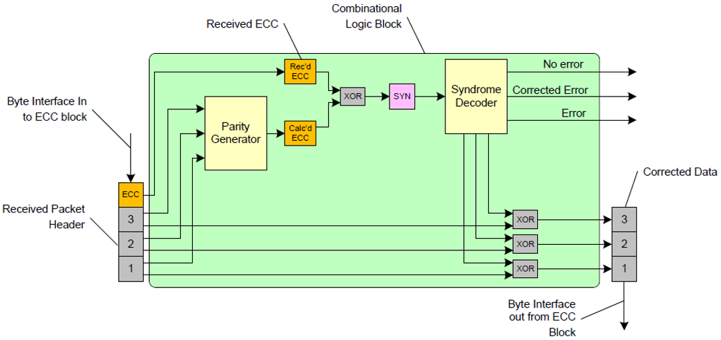
Figure 4. 24-bit ECC on RX Side Including Error Correction
2. Checksum Generation
ECC is used for detecting and correcting the header. Meanwhile, CRC is used for error detection of the entire data packet. Each data packet will calculate a checksum (checksum).
MIPI CSI-2 uses a 16bit CRC, with the generating polynomial as follows:
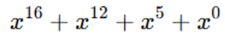
The CRC result is transmitted as the tail of the data packet. If WC=0, then CRC is set to 0xFFFF.
The calculated checksum will be sent to the receiver for verifying the correctness of the transmission.
3. Packet Spacing
MIPI CSI-2 does not transmit packets seamlessly; a segment of LPS (Low Power State) is inserted between each packet, as shown in the figure below.
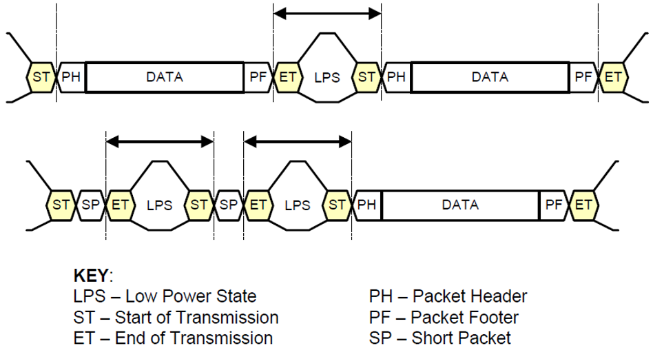
Figure 5. Packet Spacing
4. Synchronization
4.1 Frame Synchronization
During transmission, each image frame starts with a frame start packet (Frame Start, FS) and ends with a frame end packet (Frame End, FE).FS packets contain the frame start code, while FE packets contain the frame end code.
Following the FS packet, one or more long packets are transmitted, containing image data. Additionally, multiple short packets may be included for synchronization signals (Synchronization Codes).
The short data fields of the FS and FE packets will contain a 16bit frame number (Frame Number).
The frame numbers in the FS and FE packets of the same frame must be identical, so that the receiver knows they belong to the same frame.
(1) The Frame Number of 0 indicates that the frame number function is invalid.
(2) The frame number increments. Within the same virtual channel VC, each FS packet’s frame number will increment by 1 and periodically reset. For example:1, 2, 1, 2, 1, 2 or 1, 2, 3, 4, 1, 2, 3, 4.
The frame numbers in the FS and FE packets of the same frame must be identical, so that the receiver knows they belong to the same frame.
Usage Rules:
(1 Must start with FS and end with FE;
(2 The interval between the FS packet and the first data packet should be as close to the minimum packet interval as possible;
(3 The interval between the last data packet and the FE packet should also be as close to the minimum packet interval as possible.
4.2 Line Synchronization
Line synchronization is different from frame synchronization; frame synchronization is mandatory, while line synchronization is optional. However, pixel-level precision requires the use of line synchronization signals.
Similar to frame synchronization, the line start (Line Start, LS) and line end (Line End, LE) packets’ short data fields need to contain a 16bit line number (Line Number).
The line numbers in the LS and LE packets of the same line must be identical.
Line Number is a logical number and does not necessarily equal the actual physical line number.
(1) The Line Number of 0 indicates invalid;
(2) The line number increments: within the same virtual channel VC and data type DT, each LS packet’s line number increments by 1. In a new frame, it resets to 1.
Note: According to MIPI01 specifications, the receiver should be able to handle line effect periods close to 0.
Recommended Learning Materials:
“Specification for Camera Serial Interface 2 (CSI-2)” (PDF version available by messaging “CSI2” on WeChat)
Follow the WeChat public account “Chip Strategy” for more technical materials and sharing!
Here, we will share knowledge related to chip design, cutting-edge technology, and industry trends, looking forward to communicating and discussing with you for mutual progress!