In the previous article of this series, we introduced the visual function library. In this article, we will guide you through the installation and usage of cameras.
In both AI deep learning and IoT applications, visual processing occupies a significant usage proportion, and cameras are the most commonly used data source devices. This article will lead you to install a camera for Jetson Nano 2GB and test the camera using some tools and simple code.
The Jetson Nano 2GB developer kit supports CSI cameras, USB cameras, and network cameras.
This article mainly targets beginners, so we will focus on the more suitable devices: CSI cameras and USB cameras. We will not discuss more complex cameras like GigE at this time.
How to Choose a CSI or USB Camera for Jetson Nano 2GB
Before choosing a camera, we can check the following website:
https://www.elinux.org/Jetson_Nano#Cameras
This site lists the camera models officially recommended by NVIDIA. Generally, USB interface cameras are driver-free and do not require further explanation.
However, CSI interface cameras vary significantly depending on the sensor chip, and not all CSI cameras support the Jetson Nano product, so be sure to pay attention to this issue when purchasing. Currently, the commonly used CSI camera on Jetson Nano is the Raspberry Pi V2 camera (the sensor chip is IMX219).
In this article, we will use the following model:
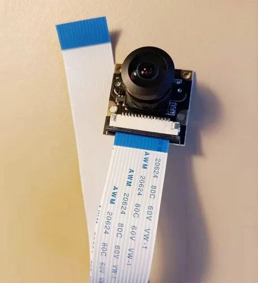
【Note】 The CSI camera does not support plug-and-play, so it must be installed before powering on for the system to recognize the CSI camera. If installed after powering on, it may cause the Jetson Nano 2GB to fail to recognize the camera and pose other risks; therefore, please avoid installing the camera while powered on.
Installing the CSI Camera
The Jetson Nano 2GB has a CSI camera interface, located and shaped as shown in the figure below.
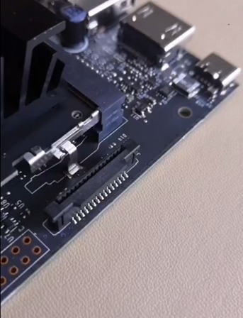
Before installing the camera ribbon cable, we must first pull up the latch above. Please be particularly careful not to break this small plastic piece, as it will affect the warranty.
Pay attention to the direction of the ribbon cable during installation.
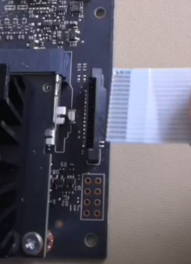
The part with the golden fingers (metal pins) must face the CSI interface, and the side with the pin header of the camera interface, and carefully push the ribbon cable all the way in; otherwise, there may be contact issues. Finally, gently close the latch, and the installation is complete!
Testing the Camera
After installing the camera, we need to check whether it has been installed correctly.
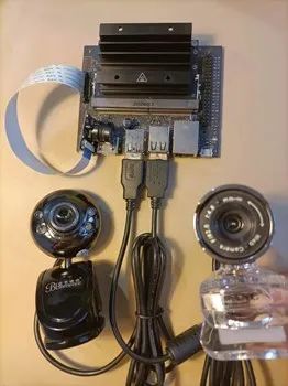
For demonstration purposes, we installed 1 CSI camera and 2 USB cameras:
The simplest test command is as follows:

If the camera is functioning correctly and installed properly, this command will display the current number of installed cameras. As shown in the screenshot below:

You will see a list of individual devices, but this information is too sparse to determine which number corresponds to which camera.
To further test the number of cameras and detailed specifications, you will need the v4l2-utils tool to assist. The installation method is very simple, as shown in the command below:

After installation, you can use the following command to detect more complete information:

In this example, executing this command will show the following screenshot information, clearly listing all three cameras:
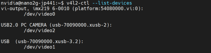
Here, you can clearly see that the first (/dev/video0) belongs to the imx219 specification (CSI) camera, the second (dev/video2) is a USB2.0 camera connected to xusb-2 (specification is USB3) interface, and the third (/dev/video1) is a USB camera connected to xusb-3.2 (specification is USB2) interface, allowing you to easily identify which number corresponds to which camera.
You can also use this command to further detect the more detailed specifications of each camera, including the supported image types, dimensions, frame rates, etc., which are important when using the code later.
Please execute the following command to view the specifications of the first CSI camera:

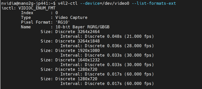
This provides a more precise list of the camera’s detailed parameters, such as the displayed “RG10” representing the data format of this camera, and the “10-bit Bayer RGRG/GBGB” below further explains the algorithm and channel parameters used for this format.
Below the dimensions, for example, 3264×2464, there are also corresponding Interval performance parameters, indicating the supported resolutions and the maximum execution frame rates for those resolutions. This information is essential for us to use as a basis for setting up applications later.
For other devices, please modify accordingly.
In the next article, we will teach you how to call the camera, so stay tuned!
Recommended Reading
NVIDIA Jetson Nano 2GB Series Article (1): Unboxing Introduction
NVIDIA Jetson Nano 2GB Series Article (2): Installing the System

NVIDIA Jetson Nano 2GB Series Article (3): Network Settings and Adding SWAPFile Virtual Memory

NVIDIA Jetson Nano 2GB Series Article (4): Experiencing Parallel Computing Performance

NVIDIA Jetson Nano 2GB Series Article (5): Experiencing the Visual Function Library


NVIDIA Chief Scientist BILL DALLY interprets how NVIDIA’s new technology helps address the significant challenges facing the world today through a keynote speech at the GTC China online conference 2020. Quickly click “Read Original” or scan the QR code in the poster below to watch the speech video!