Mean filtering is a fundamental digital signal processing technique commonly used for image and signal denoising. This article will detail how to implement a simple yet efficient mean filter using the Verilog hardware description language.
Basic Principles of Mean Filtering
The core idea of mean filtering is to replace the value of a pixel with the average value of its surrounding neighborhood. For a 3×3 neighborhood, the calculation formula is as follows:
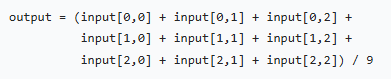 This method can effectively reduce random noise but may cause slight blurring of image edges.Implementation Method
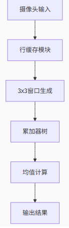
Design Description
This mean filter implementation includes the following key components:
Row Buffer Mechanism:Two row buffers are used to store the previous two rows of data, along with the current row data to form a 3×3 window.
-
3×3 Window Construction:Using pixel buffers and row buffers, extract the 9 pixel values surrounding the currently processed pixel.
-
Summation and Average Calculation:Add the 9 pixel values and divide by 9 to obtain the average. Here, a right shift of 3 bits (dividing by 8) is used as an approximation to dividing by 9 to improve hardware efficiency.
-
Pipelined Design:To enhance processing speed, a pipelined structure is adopted, ensuring that one pixel can be processed per clock cycle.
Processing Results:
Original Image

Image After Mean Filtering

Follow our public account to join the QQ group
To obtain the source code for the filtering module, please join the QQ group!