In industrial sites, various analog sensors such as pressure, displacement, temperature, flow, and speed differ in their design and technical methods. The power distribution methods for sensor operation are mainly divided into two-wire and four-wire systems, and the output analog signals also vary, with common signals being 0-20mA, 4-20mA current signals, and 0-75mV, 0-5V, 1-5V voltage signals.
To successfully collect the analog signals from various sensors into PLC/DCS/FCS/MCU/FA/PC systems, it is necessary to match the selection based on the functions and technical characteristics of the sensors and the data acquisition systems. Additionally, the differences in power supply between the sensors in the industrial field and data acquisition systems like PLCs, as well as various EMC interference impacts, must be considered. Typically, the analog signals output by the sensors are isolated, amplified, and converted before being sent to data acquisition systems like PLCs. The PLC collects the analog or digital signals from the sensors through signal lines and processes them. If the sensor outputs an analog signal, the PLC must connect to an analog input interface; if the sensor outputs a digital signal, the PLC must connect to a digital input interface.
Switching Sensors are contactless switches that can serve as the switching input signals for PLCs. They are generally used in devices that require switching control, such as machine tools and machinery. Analog sensors convert different physical quantities (such as pressure, flow, temperature) into analog quantities (4-20mA current or 1-5V voltage). Analog sensors serve as input signals for the analog input modules of PLCs and are generally used in process control. Digital sensors refer to sensors that have been modified or equipped with A/D conversion modules to output digital signals (or digital codes). They mainly include amplifiers, A/D converters, microprocessors (CPUs), memory, communication interface circuits, etc.
Common analog sensors are divided into two-wire and four-wire systems. Both systems have only two signal wires, and their main difference is that the two-wire system’s two signal wires provide power to the sensor or transmitter while also providing the current voltage signal; whereas the four-wire system’s two signal wires only provide the current signal. Typically, sensors or transmitters that provide two-wire current voltage signals are passive; while those providing four-wire current signals are active. Therefore, when the input channel of the data acquisition system like PLC is set to connect to a four-wire sensor, the PLC only collects the analog signal from the terminal of the input channel. When the input channel is set to connect to a two-wire sensor, the PLC’s analog input channel must also output a DC 24V power supply to drive the two-wire sensor.
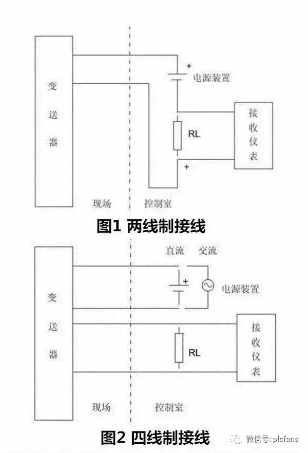
The 4-20mA signal is related to electrical standards; the 4-20mA signal system is the international standard for analog signals in process control systems set by the International Electrotechnical Commission (IEC). In China, this international standard signal system has been adopted since the DDZ-Ⅲ type electric instrument, where the instrument transmits signals using 4-20mA, and communication signals use 1-5VDC, meaning a current transmission and voltage reception signal system. Since the starting current of the signal is 4mA, it provides a static working current for the transmitter, and the electrical zero point of the instrument is 4mA, which does not coincide with the mechanical zero point. This active zero point is beneficial for identifying faults such as power outages and disconnections.
Selection Based on the Performance of Analog Signal Sensors
1. Two-wire current/voltage output sensors (no power supply, powered by the load providing 16-24V distribution, outputting 4-20mA/0-5V).
1.1 Two-wire passive 4-20mA input sensors are connected to the PLC after being powered by a current isolator. As shown in Figure 1, the positive terminal of the weighing and distance measuring sensor connects to 16-24VDC, and the negative terminal outputs 4-20mA current.
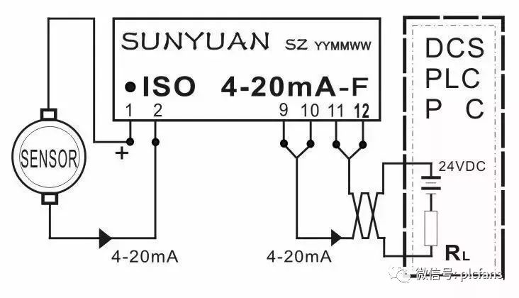
Figure 1 Typical Application Diagram of Two-wire 4-20mA Isolated Power Distribution Device
1.2 Two-wire passive voltage signal input sensors are connected to the PLC after being powered by a voltage distributor. As shown in Figures 2 and 3, the positive and negative terminals of the displacement and electronic ruler sensors connect to 16-24VDC voltage.
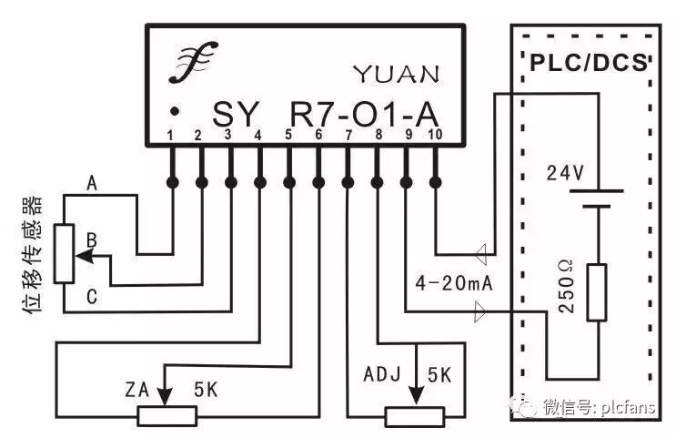
Figure 2 Non-isolated Two-wire Passive Voltage Distributor
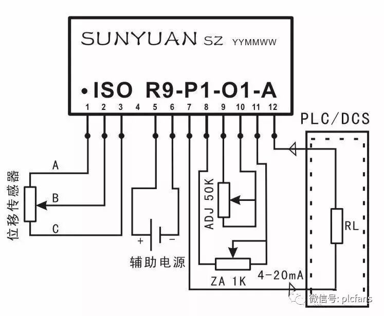
Figure 3 Isolated Voltage Distributor
As shown in Figures 4 and 5, the stress gauge and weighing bridge sensors connect the positive and negative terminals to 16-24VDC voltage.
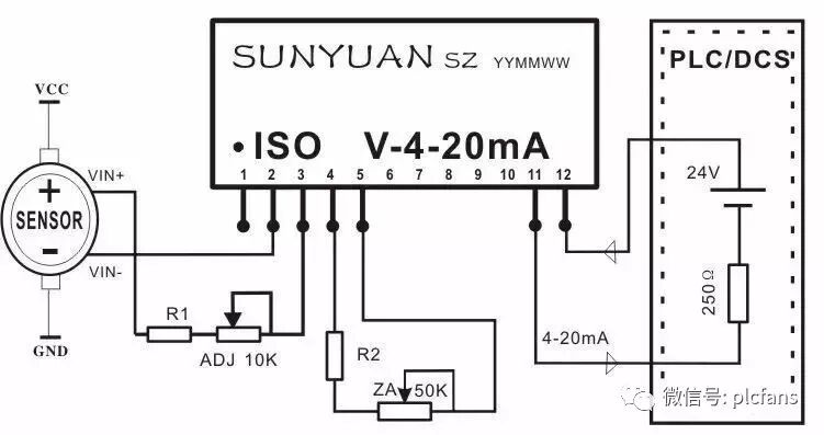
Figure 4 Isolated Voltage Signal Conversion Amplifier
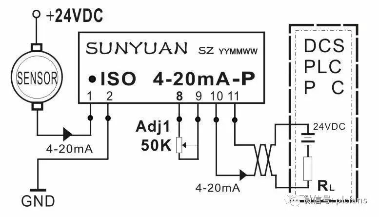
Figure 5 Isolated Bridge Voltage Distributor
1.3 Two-wire sensors outputting 4-20mA current loops are connected to the PLC after isolation by an isolator. As shown in Figure 6, the positive terminal of the pressure and flow sensors connects to 9-32VDC, and the negative terminal outputs 4-20mA current.
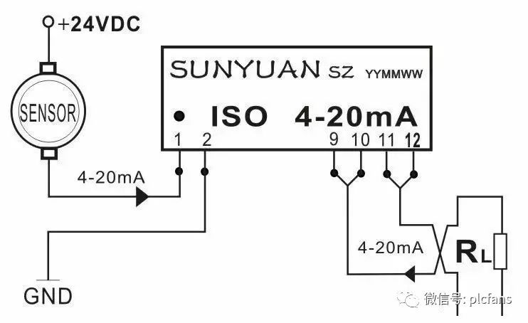
Figure 6 Typical Application Diagram of Two-wire 4-20mA Current Loop Isolator
1.4 Two-wire sensors outputting 4-20mA current are connected to the PLC after isolation conditioning matching (to resolve input-output conflicts). As shown in Figure 7, the positive terminal of the temperature and speed sensors connects to 12-24VDC, and the negative terminal outputs 4-20mA current.
Figure 7 Typical Application Diagram of Two-wire 4-20mA Signal Matching Isolation Conditioning with PLC
2. Four-wire current/voltage (input/output) type sensors (with their own power supply of 24VDC, input/output: 4-20mA or 0-5V).
2.1 Four-wire current output type sensors are connected to the PLC after analog signal isolation amplification. As shown in Figure 8, the positive terminal of the temperature and humidity sensors connects to 24VDC, and the negative terminal outputs 4-20mA current.

Figure 8 Typical Application Diagram of Four-wire Sensor Signal I/I Isolation Amplification Connected to PLC
As shown in Figure 9, the positive terminal of the pressure and speed sensors connects to 24VDC, and the negative terminal outputs 4-20mA current.
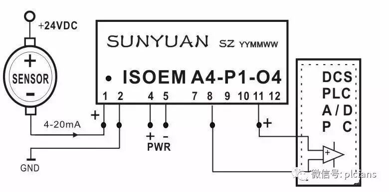
Figure 9 Typical Application Diagram of Four-wire Sensor Signal I/V Conversion Connected to PLC
2.2 Four-wire voltage output type sensors are connected to the PLC after analog signal isolation amplification. As shown in Figure 10, the positive and negative terminals of the pressure and speed sensors connect to a 24V power supply, and the output terminal outputs 0-5V voltage.
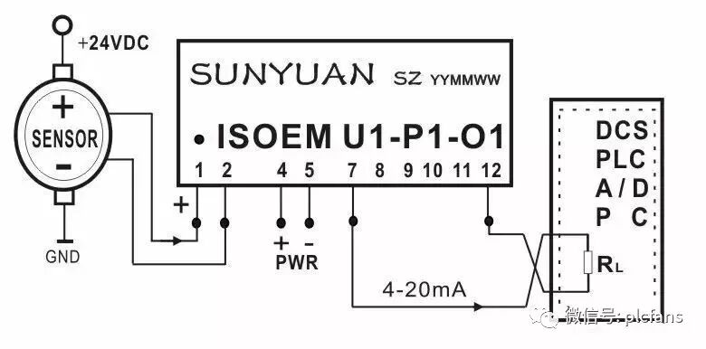
Figure 10 Typical Application Diagram of Four-wire Sensor Signal V/I Conversion Connected to PLC
As shown in Figure 11, the positive and negative terminals of the level and flow sensors connect to a 24V power supply, and the output terminal outputs 0-5V voltage.
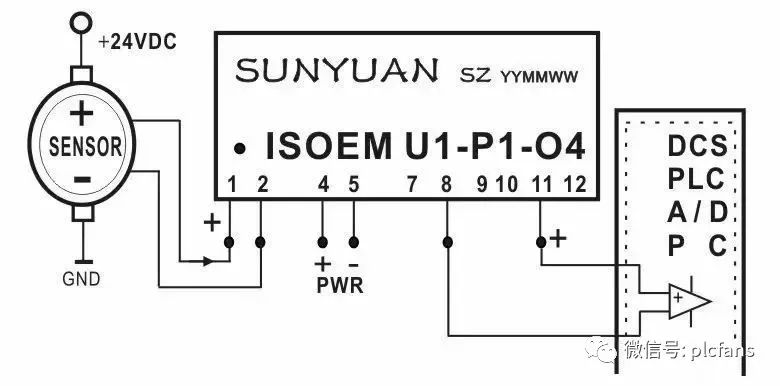
Figure 11 Typical Application Diagram of Four-wire Sensor Signal V/V Isolation Connected to PLC