 Read the latest documentation and participate:【Find Errors in Documentation and Win Prizes】 ActivityFor the latest documentation content of this article, see:https://docs.openluat.com/air724ug/luatos/app/driver/spi/
1. Introduction
SPI stands for Serial Peripheral Interface.
SPI is a high-speed, full-duplex, synchronous communication bus that only occupies four lines on the chip pins: SDI (Data Input), SDO (Data Output), SCLK (Clock), and CS (Chip Select), allowing communication between a master device and one or more slave devices. In fact, three lines can also be used (for unidirectional transmission). In embedded systems, it is mainly used for communication between EEPROM, FLASH, real-time clocks, AD converters, digital signal processors, and digital signal decoders, with transmission rates reaching over Mbps in full-duplex mode.
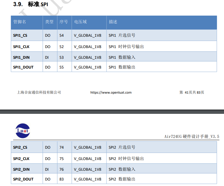
The Air724 module provides two hardware SPI interfaces, namely SPI1 and SPI2, while other SPI channels are multiplexed as LCD or MMC function pins.
2. Overview of Demonstration Functionality
This tutorial teaches you how to read and write FLASH using the SPI bus of the development board.
3. Preparing the Hardware Environment
3.1 Development Board Preparation
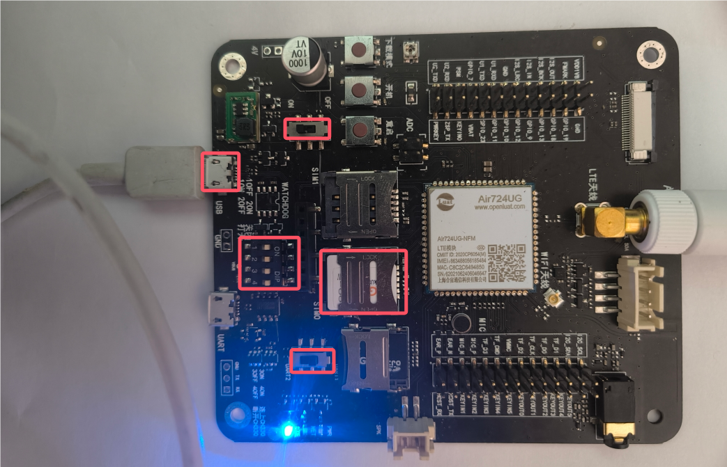
Use the EVB_Air724 development board, as shown in the figure below:
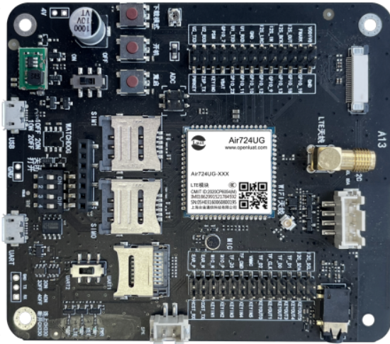
For detailed usage instructions of this development board, refer to:https://docs.openluat.com/air724ug/product/
In the Air724UG product manual, see the “EVB_Air724UG_AXX Development Board User Guide”. The latest version of the user guide at the time of writing this article is: “EVB_Air724UG_A14 Development Board User Guide”; if you encounter any issues during the use of the development board, you can refer directly to this user guide.
API documentation:https://doc.openluat.com/wiki/21?wiki_page_id=2068
3.2 Data Communication Lines
One USB data cable (micro USB).
3.3 PC Computer
Windows 7 and above versions of the Windows operating system.
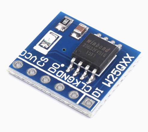
3.4 SPI FLASH Module
25Q64JVSIQ, note that the level is 3.3V
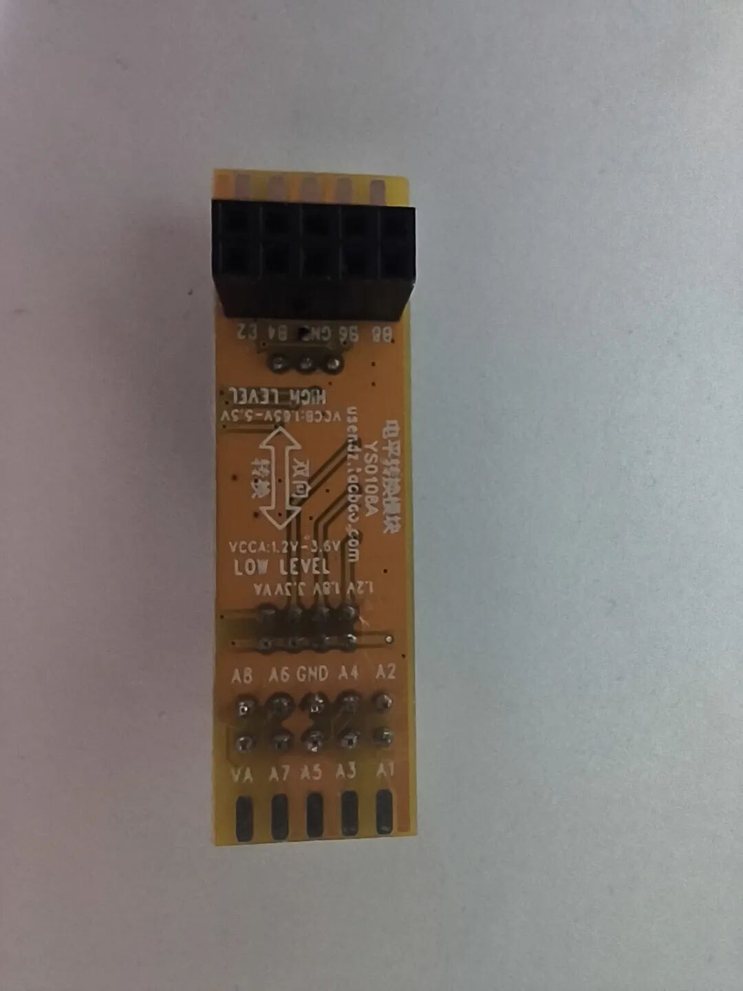
3.5 Level Conversion Module
Bidirectional level conversion module (3.3V, 1.8V)
3.6 Assembling the Hardware Environment
Insert the USB data cable into the USB port, connect the other end to the computer, set all dip switches to ON, select UART1 for the serial switch, set the USB power switch to ON for 4V, and lock the SIM card into the SIM card slot, as shown in the figure below.
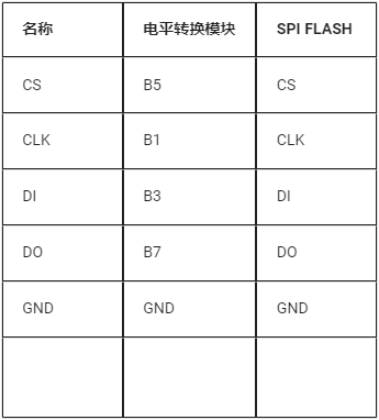
Since the SPI FLASH module only supports 3.3V levels, and the development board’s SPI interface only supports 1.8V levels, a level conversion module is required to convert the IO levels between the SPI FLASH module and the development board. The specific connection diagram is shown below.
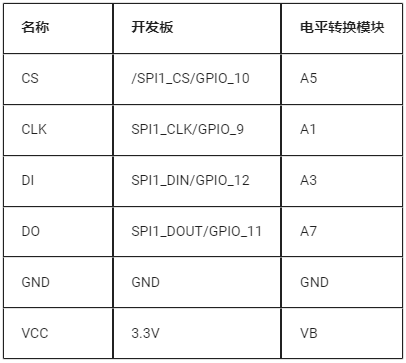
Connection between the development board and the level conversion module:
Connection between the SPI FLASH and the level conversion module:
4. Preparing the Software Environment
4.1 Download Debugging Tools
Refer to the usage instructions:Luatools Download and Detailed Usagehttps://docs.openluat.com/Luatools/
4.2 Source Code and Firmware
4.2.1 Download Low-Level Core
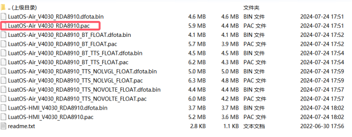
Download the low-level firmware and extract it
Link:https://docs.openluat.com/air724ug/luatos/firmware/
As shown in the figure below, the red box indicates what we will use.
4.2.2 The demo used in this tutorial can be found in the attachment:
https://gitee.com/openLuat/LuatOS-Air724UG/tree/master/script_LuaTask/demo/spiFlash
4.3 Download Firmware and Scripts to the Development Board
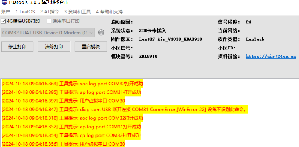
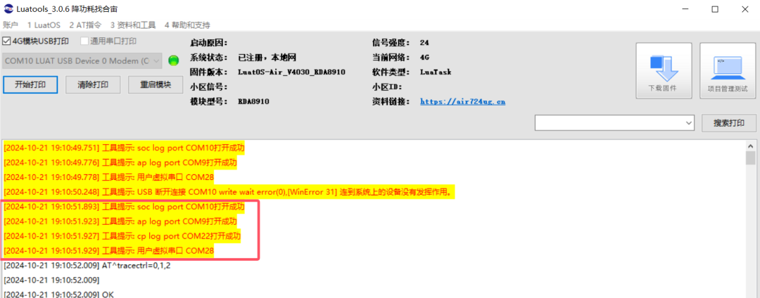
Open Luatools, power on the development board, and if the boot is successful, Luatools will print the following information.
Click on the project management test option.
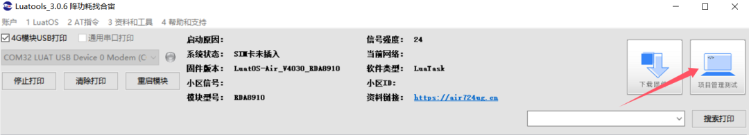
Enter the management interface, as shown in the figure below.
-
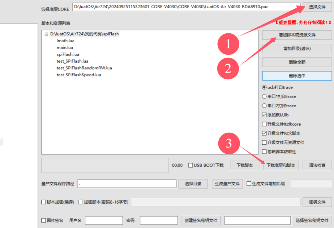
Click to select a file, choose the low-level firmware, my file is located in D:\luatOS\Air724

-
Click to add scripts or resource files, select the previously downloaded program source code, as shown in the figure below.
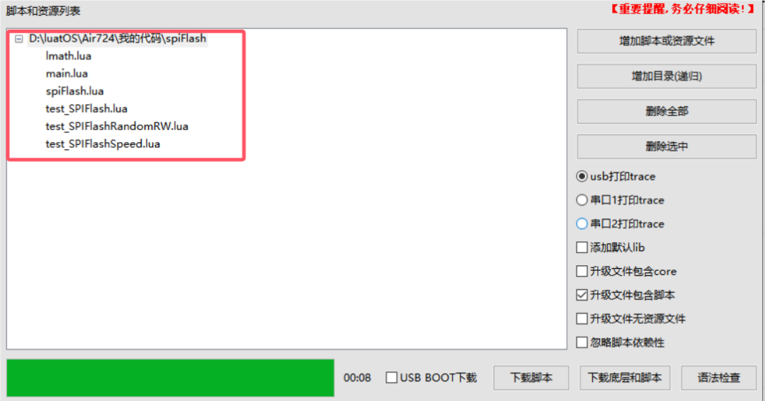
-
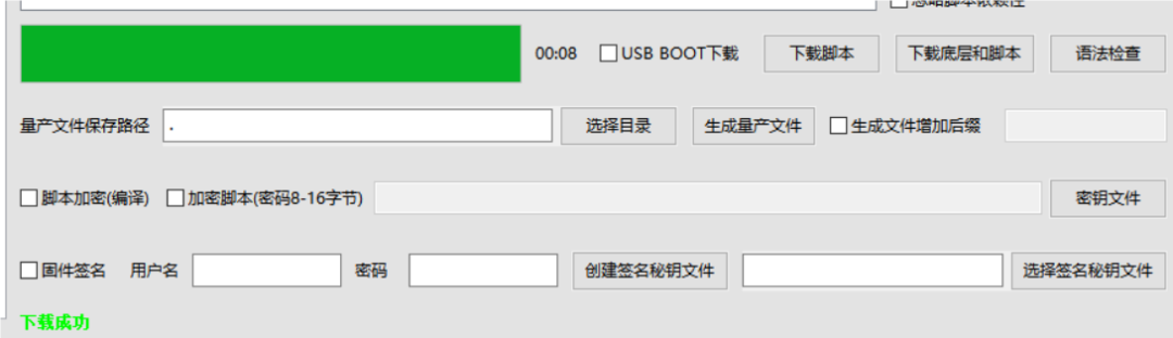
Click to download the firmware and scripts, and the download will complete as shown in the figure below.
5. Introduction to Code Examples
5.1 API Description
5.1.1 Enable SPI Interface
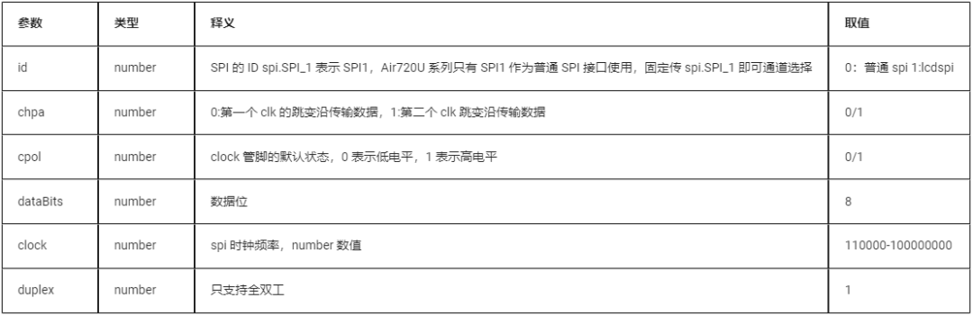
spi.setup(id,chpa,cpol,dataBits,clock,duplex)
(Click to enlarge)
Return value
5.1.2 Write Data to SPI
spi.send(id,data[,cscontrol])
(Click to enlarge)
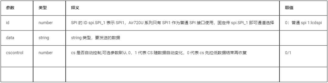
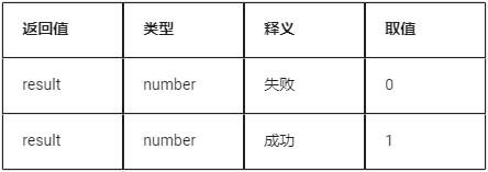
Return value
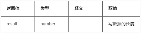
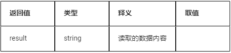
5.1.3 Read Data
spi.recv(id,length[,cscontrol])
(Click to enlarge)
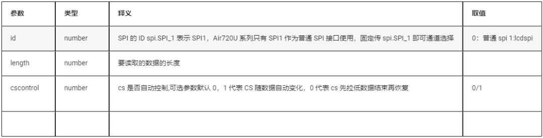
Return value
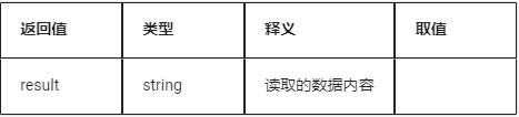
5.1.4 Read and Write Data
spi.send_recv(id,data[,cscontrol])
| Parameter | Type | Description | Value |
| id | number | SPI ID, spi.SPI_1 indicates SPI1, the Air720U series only has SPI1 as a normal SPI interface, so always use spi.SPI_1 for channel selection | 0: normal spi 1: lcdspi |
| data | string | Data to be sent | |
| cscontrol | number | Whether CS is automatically controlled, optional parameter default 0, 1 means CS changes automatically with data, 0 means CS is pulled low before data ends and then restored | 0/1 |
Return value
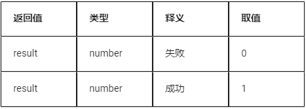
5.1.5 Close SPI
spi.close(id)
| Parameter | Type | Description | Value |
| id | number | SPI ID, spi.SPI_1 indicates SPI1, the Air720U series only has SPI1 as a normal SPI interface, so always use spi.SPI_1 | 0: normal spi 1: lcdspi reused as normal spi |
Return value
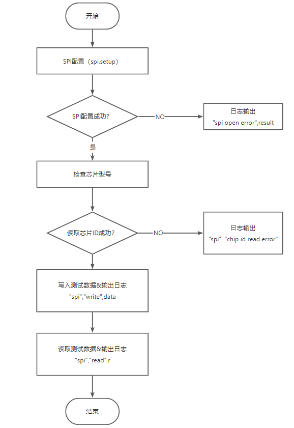
5.2 test_SPIFlash.lua Code
test_SPIFlash program flow.
5.3 main.lua Code
This code is the main program script, which will first configure the 4G network after the system starts, and then load the test_SPIFlash test module.
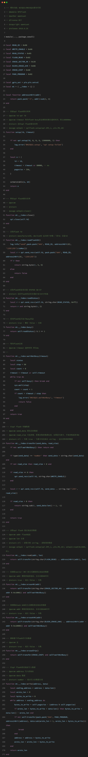
5.4 spiFlash.lua
spiFlash.lua is the driver code for W25Q32/BH25Q32.
6. Boot Debugging
6.1 Powering on the Development Board
After connecting the hardware and downloading the firmware, start the Luatools software, and the system running information will be displayed on the interface. The information printed in the red box indicates normal operation after the development board is connected to the PC, as shown in the figure below.
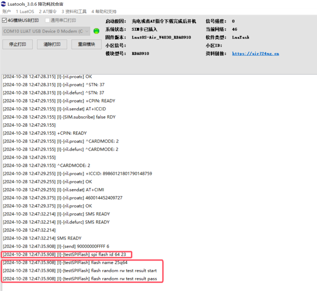
6.2 SPI FLASH Debugging
Read the SPI FLASH ID, display the model of the SPI FLASH, and perform read and write tests.
7. Common Issues
7.1 Why are there garbled characters or data loss in SPI communication?
Answer: The interface levels of SPI communication do not match. You can use an oscilloscope to observe the level status and quality during SPI communication to confirm whether the interface levels of the communication devices used by the user are consistent with the SPI1 interface level of the Air724 module, which is 1.8V. If they do not match, please ensure they are consistent. Levels that are too high or too low can cause voltage levels to be unrecognized or damage the SPI communication interface. Additionally, it is recommended to use high-speed devices as level converters to improve the signal quality of the interface levels.
7.2 What is the voltage that standard SPI can drive target chips?
1.8V, this voltage is fixed and cannot be set. If the target chip’s operating voltage is not within this range, a level conversion chip is required.

▼ Contact the Marketing Department of Hezhou ▼
Scan the QR code to add friends on WeChat/Enterprise WeChat
▼ Learn more about Hezhou ▼
4G + positioning + WiFi + Bluetooth, Air8000 industrial engineNew product launch of Hezhou Air8101 development board
Low-power Open development new solution Air780EPM