Table of Contents
Hello-FPGA CoaXPress 2.0 Host FPGA IP Core Linux Demo 4
1 Description 4
2 Device Connection 7
3 VIVADO FPGA Project 7
4 Debugging Instructions 10
Figure 1-1 Document Directory 4
Figure 1-2 VIVADO Project Directory Structure 5
Figure 1-3 SDK Project Directory Structure 5
Figure 1-4 Device Tree Information 6
Figure 1-5 Petalinux Application 6
Figure 2-1 ZCU102 Block Diagram 7
Figure 3-1 VIVADO Project 8
Figure 3-2 CPU Controller 8
Figure 3-3 CXP IP Instantiation 9
Figure 3-4 External PHY Interface, Rate Configuration via AXI Lite 9
Figure 3-5 Equalizer Chip Configuration IP 10
Figure 3-6 Width and Protocol Conversion IP 10
Figure 4-1 Installing Kernel Driver 11
Figure 4-2 CXP Demo SDK Software Project Directory 11
Figure 4-3 Configuring TCF Agent 12
Figure 4-4 Basic Test UDP Test Program 200 Frames Per Second 12
Table 1-1 LINK Rate Configuration 7
Hello-FPGA CoaXPress 2.0 Host FPGA IP Core Linux Demo
Description
This manual is for the Hello-FPGA CoaXPress 2.0 HOST FPGA IP Core demo project, which demonstrates the usage and configuration process of the IP.
The features of the demo are as follows:
- The demo runs a Linux application using UDP communication, with a UDP server program running on Linux and a client program running on a Windows computer to control the acquisition and monitor the captured images, achieving the demonstration purpose.
- The current code is suitable for the ALINX Z19 evaluation board; please contact us for other ZYNQ evaluation boards.
- Use VIVADO 2020.2, Petalinux 2020.2, Xilinx SDK 2019.1 (please upgrade if using other versions).
- The VIVADO project is provided in block design format.
- LINK is configured for 1 camera and 4 LINKS, with 0x38 configuration during device discovery, i.e., 3.125Gbps, and 0x48 configuration during device acquisition, i.e., 6.125Gbps. If the camera does not support the corresponding rate, please modify the code for testing. Note that the current Z19 program does not support 10Gbps and 12.5Gbps rates.
- Using ZYNQ PS A53 as the CPU controller, equipped with a custom Petalinux Linux system, software code is developed and debugged using SDK.
- The IP is provided in netlist form, and parameters cannot be modified. For different LINK configurations, please contact Info@hello-fpga.
- Other related IPs are provided in encrypted form.
File List:
Z19 Top-Level Folder
cxp_host_ps Example FPGA Project
IPLib Project Dependency Files
Z19 Evaluation Board Documentation
IP User Manual
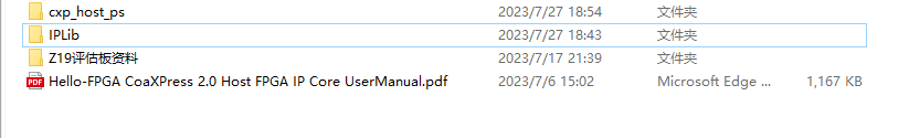
Figure -1 Document Directory
The following figure shows the internal directory structure of cxp_host_ps. You can directly open the *.xpr project file with VIVADO 2020.2, where the cxp_host_wrapper.xsa file is the precompiled and exported hardware description file. Users can use this file to create and compile the petalinux project.
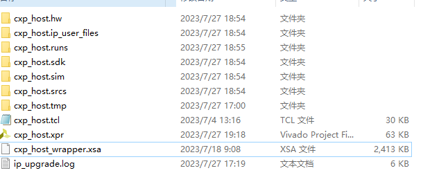
Figure -2 VIVADO Project Directory Structure
The following figure shows the internal directory structure of the petalinux precompiled design. You can directly configure it using petalinux. Users can modify the device tree, ROOTFS, or replace the bit file, or recreate the project.
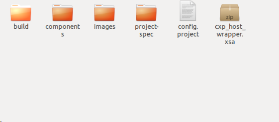
Figure -3 SDK Project Directory Structure
The command to create the project is as follows:
petalinux-create -t project -n petalinux –template zynqMP
The current device tree information is as follows:
Here, the memory manually specifies a 4GB address space (the actual usable memory for Z19 is 8GB), where the starting address is 0x8_0800_0000, with a length of 0x7000_0000 reserved for PS internal use for continuous DMA transmission. Users can add content based on this, increasing the memory range, but do not delete content, as it may cause the device to fail to boot or DMA transmission errors.
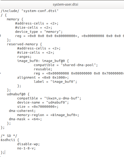
Figure -4 Device Tree Information
The following figure shows the petalinux application, where CXP_Core is the output dynamic library project, and cpp_demo is the demo program that calls the CXP_Core dynamic library to complete camera configuration, acquisition, DMA transmission, and UDP monitoring.
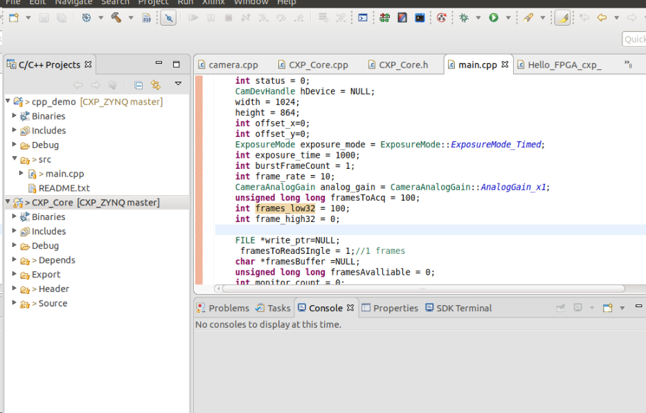
Figure -5 Petalinux Application
Table -1 LINK Rate Configuration
|
Rate Configuration |
Downlink Rate |
Maximum Rate |
|
0x28 |
1.250 Gbps |
1.000 Gbps |
|
0x30 |
2.500 Gbps |
2.000 Gbps |
|
0x38 |
3.125 Gbps |
2.500 Gbps |
|
0x40 |
5.000 Gbps |
4.000 Gbps |
|
0x48 |
6.250 Gbps |
5.000 Gbps |
|
0x50 (1) |
10.000 Gbps |
8.000 Gbps |
|
0x58 (1) |
12.500 Gbps |
10.000 Gbps |
Device Connection
The devices include:
- Camera, please connect the power supply according to the manufacturer’s requirements;
- Connect the Camera to the CXP HOST FMC sub-card, ensuring the LINK numbers correspond one-to-one, using CXP coaxial cables for the connection;
- Connect the CXP HOST FMC to Z19 FMC1, and secure it with screws after connection;
- The demo uses SD card boot mode, please set Z19 to boot from the SD card;
- The demo requires a network connection; please connect the Windows UDP client computer to the same local area network as Z19.
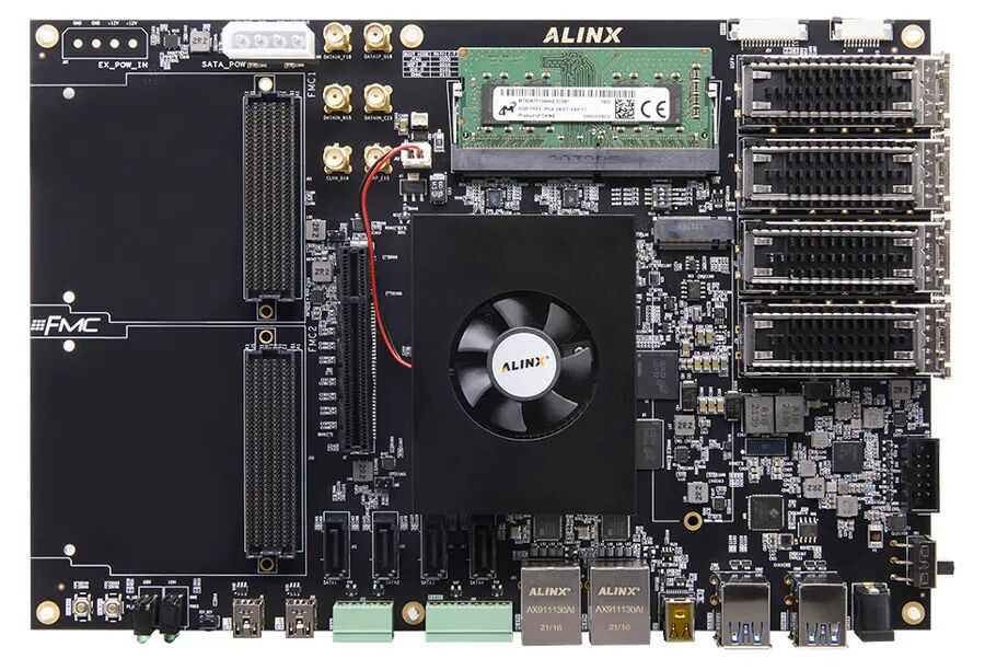
Figure -1 Z19 Evaluation Board
VIVADO FPGA Project
Open using VIVADO 2020.2.

Figure -1 VIVADO Project
As shown in the figure below, the CPU uses Xilinx’s FPGA hard-core processor PS, and the CPU is connected to peripherals via the AXI bus, where cxp transmits data directly using PS memory for DMA operations.
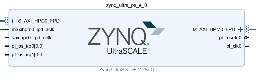
Figure -2 CPU Controller
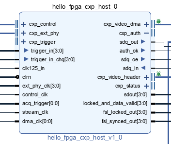
Figure -3 CXP IP Instantiation
The demo uses an external PHY, with dynamic rate configuration completed via AXI lite interface.
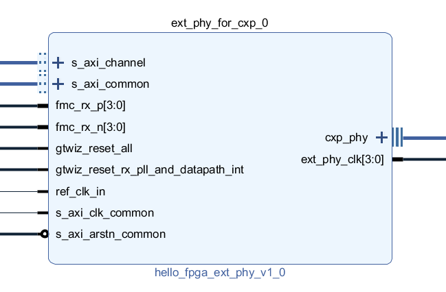
Figure -4 External PHY Interface, Rate Configuration via AXI Lite
The following figure shows the equalizer configuration IP. The equalizer is a set of chips on the FMC interface board used to equalize high-speed downlink signals. Different rates will have different parameter configurations; please refer to the software demo for specific configuration logic.
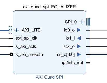
Figure -5 Equalizer Chip Configuration IP
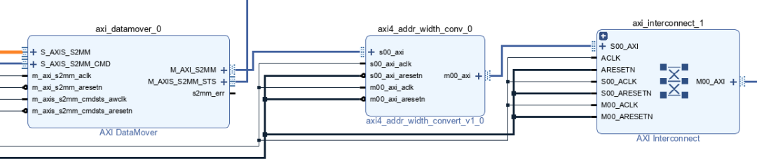
Figure -6 Width and Protocol Conversion IP
Compile according to the normal process. If the code has been modified, the hardware information needs to be exported to the SDK after changes.
Debugging Instructions
The following figure shows the Linux application project, where CXP_Core is the driver code used in conjunction with the FPGA project. The code outputs a dynamic library, which should be copied to the Linux lib directory after generation.
This code has the following limitations:
- Fixed use of 4 LINK connections;
- The base address of the PL peripheral module has been defined in the driver, so the FPGA part cannot modify the corresponding address allocation. Modifications will cause the driver program to crash Linux.
Before debugging, you need to:
- Connect the device to the network and use ifconfig to check the IP address;
- Install the DMA driver, which has been precompiled, and the necessary dynamic library libDMACore.so has been placed in the Linux lib directory. If you need to change the SD card, please copy this dynamic library as well; the command to install the DMA driver is insmode u-dma-buf.ko. It should be noted that this kernel driver is not compiled into the Linux kernel, so the demo needs to install it each time it boots.
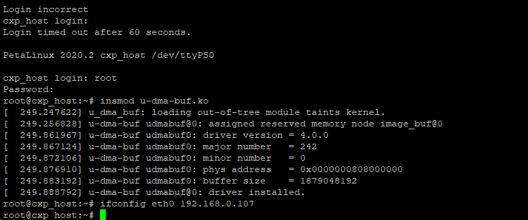
Figure -1 Installing Kernel Driver
- The LibCXP_Core dynamic library has been pre-placed in the Linux lib directory. If you need to change the SD card, please copy this dynamic library as well;
Figure -2 CXP Demo SDK Software Project Directory
For debugging, it is recommended to use TCF Agent to download the debugging program. Before debugging, first test the connection to ensure it is smooth. The debugging program is cpp_demo, not the CXP_Core program. After starting debugging, please disable breakpoints to ensure the program executes smoothly as expected.
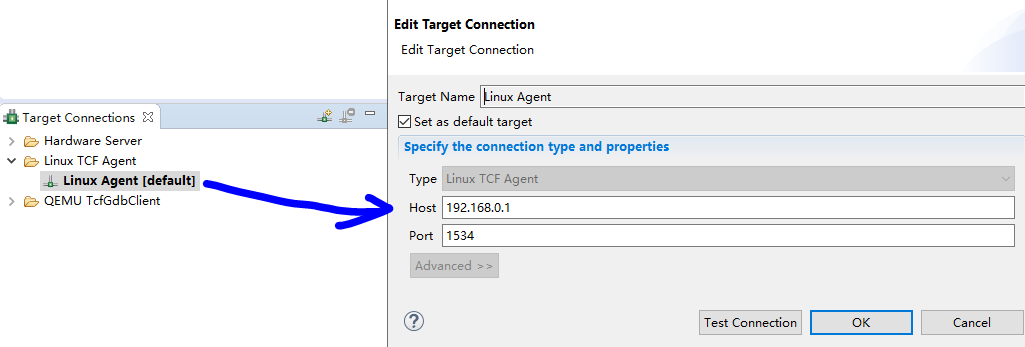
Figure -3 Configuring TCF Agent
The program will output print information to the PS UART serial port.
After running the cpp_demo program and disabling breakpoints, you can open the test program basic_test on the Windows computer, then start the test and monitor the working status of the ZYNQ CXP device. Note that this demo does not transmit images in real-time; it only monitors images, limited by network transmission speed and other conditions.

Figure -4 Basic Test UDP Test Program 200 Frames Per Second