
Abstract: In the wheeled category of the Indonesian Wheeled Soccer Robot Competition (KRSBI), participating robots must be able to complete designated tasks, one of which is to chase and catch the ball. Omnidirectionality is one of the methods used for navigation in mobile robot applications that require all-around movement. Since this movement is designed to occur without changing the robot’s orientation, omnidirectional wheels that can move freely in two directions are employed. This mobile robot features three omnidirectional wheels, each equipped with a DC motor for propulsion. The DC motors are driven by an EMS 30A H-bridge, with an Arduino Mega 2560 serving as the main microcontroller for control. By utilizing omnidirectionality and inverse kinematics calculations, the mobile robot’s velocity and direction in the x, y directions, as well as its angular velocity around the z-axis, are controlled, thereby determining the motion parameters s1, s2, and s3 for each wheel. The length from the wheel axis to the center of the robot’s body is 160 mm. In this study, the robot’s ability to move forward, backward, sideways, and diagonally was achieved. According to data evaluation, the angular error of the omnidirectional robot’s movement was 2.84% at speeds ranging from 0.256 m/s to 1.403 m/s.
Original Authors: Riky Tri Yunardi, Deny Arifianto, Farhan Bachtiar, Jihan Intan PrananingrumEditor: AutoGo

01
Introduction
The mobile robot is designed to traverse various environments and autonomously determine its movement path. Depending on the motion system, mobile robots can be classified into wheeled robots and legged robots. However, in the Indonesian Wheeled Soccer Robot Competition (KRSBI), wheels that can move more freely and operate on flat surfaces must be used. The robot must complete programmed tasks, one of which is to search for and catch the ball.
In the wheeled soccer robot category, the robot should kick the ball on the field like a soccer player. However, the robot has movement limitations; it cannot accurately move in the desired direction, and there are issues with the robot’s directional positioning and motion control. The inability to move left, right, and diagonally without changing direction limits the robot’s ability to kick the ball effectively, making it difficult to complete the designated tasks.
The three-wheeled omnidirectional mobile robot is one of the most widely used types of mobile robots. Compared to traditional two-wheeled and four-wheel drive robots, omnidirectional mobile robots have many advantages, such as flexible movement patterns and the ability to move freely in two directions. The motion mechanism of the soccer robot employs omnidirectional wheels, allowing the robot to travel in any direction at the same speed and acceleration, which is very helpful for responding to the ball’s different positions on the field. The omnidirectional design suitable for the robot uses a three-wheel configuration, with each wheel mounted at an angle of 120 degrees from each other, allowing the wheels to rotate either perpendicular or parallel to the direction of movement.
This study applies the omnidirectional method to the omnidirectional mobile robot. It adopts a three-wheel omnidirectional configuration to enhance the mobile robot’s ability to move in any direction and at any angle. The three-wheel configuration provides the robot with omnidirectional mobility without the need for traditional drive systems. The study also introduces an inverse kinematics model and adapts the robot’s dimensions in conjunction with the omnidirectional wheel drive. DC motors are used to drive the differential motion of the omnidirectional wheels, and to obtain the speed of each wheel, the inverse kinematics formula must first be derived. Trajectory tests are conducted to determine the robot’s ability to travel in the reference direction.
02
Omnidirectional Mobile Robot
(1) Omnidirectional Motion System
Omnidirectional motion refers to the robot’s ability to move in any direction. In mobile robots, the space occupied is composed of three dimensions: x, y (the robot’s position on the plane), and ∞ (the robot’s direction). In geometric robotics, using the omnidirectional motion method, the robot can move in any direction without considering its position and orientation, thus simultaneously generating linear velocities Vx and Vy. By applying the omnidirectional motion method, these values can be adjusted, allowing the robot to have three degrees of freedom (DOF).
(2) Complete Motion System
A complete motion system is one where the number of degrees of freedom equals the number of coordinates used to define the system configuration. When applied to robots, a complete motion system does not require knowledge of the actual form of the mechanism. In a planar field, a mobile robot with three degrees of freedom is a complete motion robot. A complete motion system aids in planning the robot’s movement, as the robot’s motion is unrestricted.
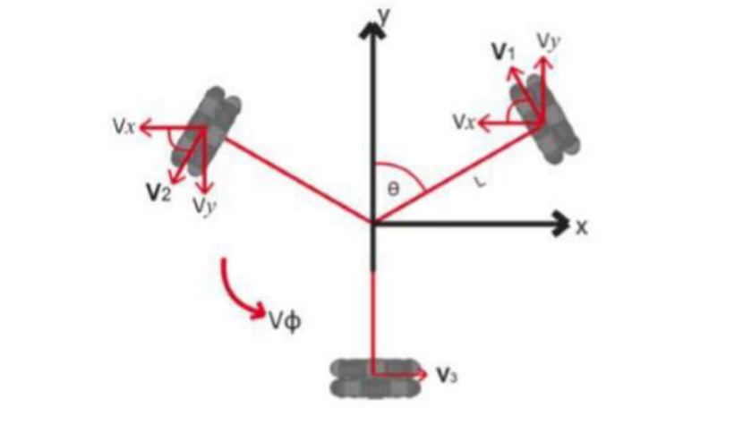
Figure 1. Omnidirectional Three-Wheel Configuration
The omnidirectional concept is used to determine angles, where α is the angle of the motor shaft drawn from the x-axis of the robot coordinate system. α1= 30°, α2 = 150°, α3 = 270°. As shown in Figure 2, the angle between the drive shaft of the wheel and each α is 90° (i.e., π/2). To decompose the vector into x and y components, we use some simple trigonometric functions.
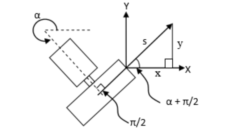
Figure 2. Concept of Wheel Trigonometric Functions
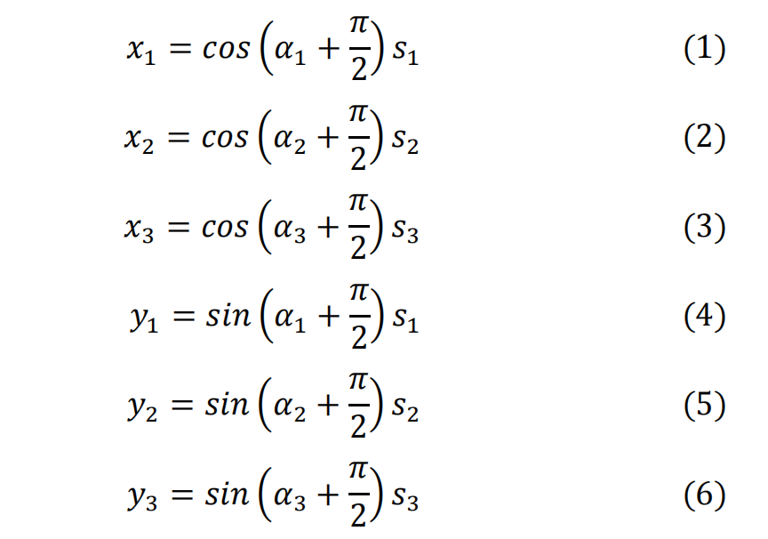
For each of the three wheels, the x and y components of the robot’s direction are described by formulas (1) to (6):
Additionally, there is a rotational component ω, which allows the robot to rotate around its z-axis. The robot’s rotation is simply the sum of the speeds of each motor. Even if the motors rotate in opposite directions, the total rotation of the robot can usually be obtained. The robot’s rotational speed ω can be calculated using the motor speed formula (7):

(3) Inverse Kinematics
Inverse kinematics is used to measure the angular velocity of the wheels. In this study, the inverse kinematics method is used to determine the speed of the DC motors. The inverse kinematics formula for a robot with three wheels is defined as formula (8):
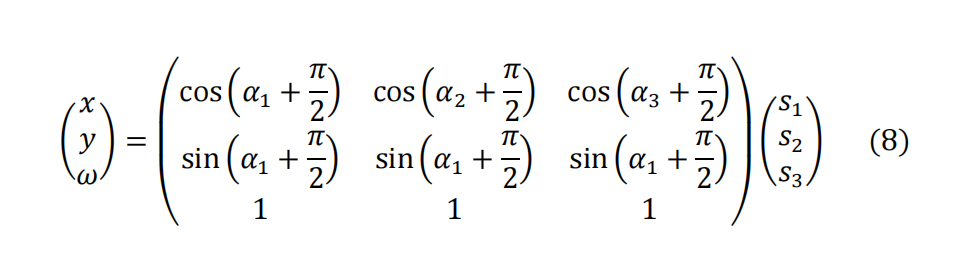
Where s1 is the speed of motor 1, s2 is the speed of motor 2, s3 is the speed of motor 3. x is the speed in the x-axis direction, y is the speed in the y-axis direction, and the corresponding values for the robot’s rotation are 1, -1, and 0.
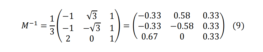
Taking the inverse of formula (1) yields formula (9):
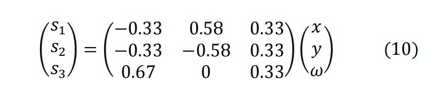
Then we obtain:
03
Materials and Methods
(1) Omnidirectional Wheels
The uniqueness of omnidirectional wheels lies in their ability to move independently in two directions. These wheels are typically circular and can move laterally along the wheel’s outer diameter using rollers. Omnidirectional wheels can transform a non-complete constrained robot into a complete constrained robot. A non-complete constrained robot using ordinary wheels has only 2 operational degrees of freedom, such as moving forward, backward, and rotating. In contrast, a complete constrained omnidirectional wheel should be able to solve this issue, as it has 3 degrees of freedom. Unlike non-complete constrained robots, complete constrained omnidirectional mobile robots can move in any direction without changing the wheel’s orientation, enabling forward, backward, lateral sliding, and rotation in place. Figure 3 shows the omnidirectional wheel.
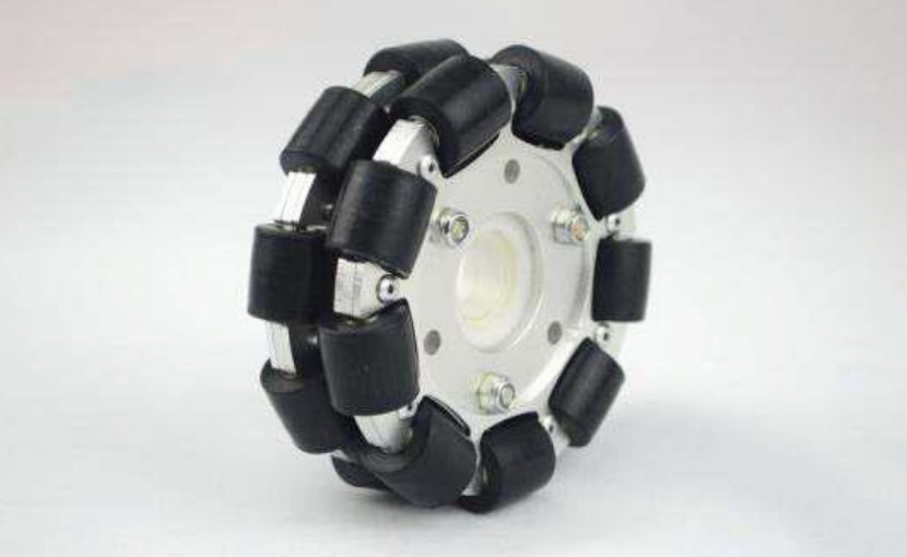
Figure 3. Omnidirectional Wheel
(2) PG-45 DC Motor
A DC motor is a motor that uses direct current voltage as input. DC motors are widely used in the design of mobile robots. The PG-45 motor has a rated voltage of 24 volts and can produce a speed of 3250 revolutions per minute. When connected to a 24-volt power source, this motor generates a power of 22.5 watts and a current of 0.2 amps.
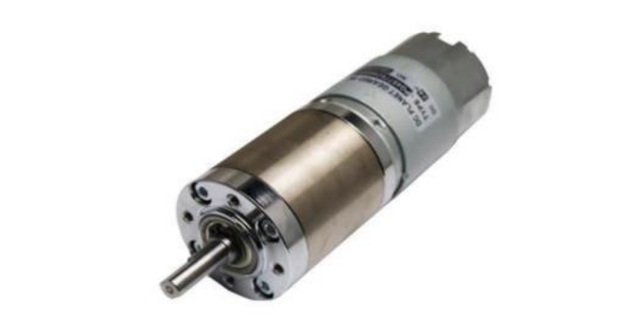
Figure 4. PG-45 DC Motor
(3) EMS 30A H-Bridge
The EMS 30A H-bridge is an H-bridge driver designed to provide up to 30 amps of continuous current in both directions at voltages ranging from 5.5 volts to 16 volts. This module is equipped with a load current sensor circuit that can provide feedback to the controller.
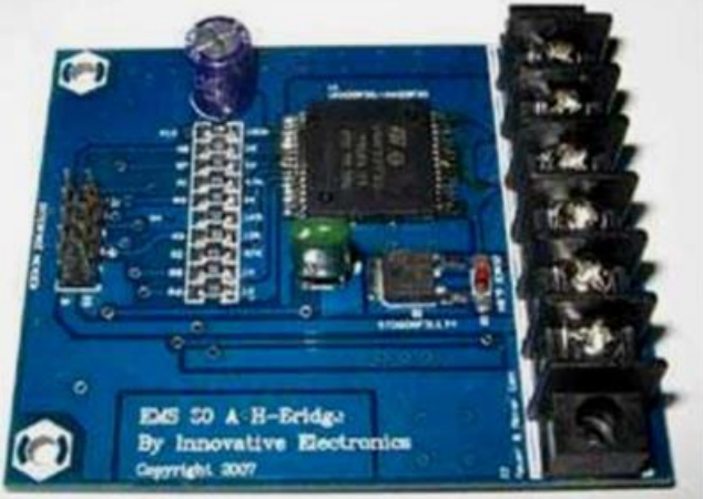
Figure 5. EMS 30A H-Bridge Module
(4) Arduino Mega 2560
The Arduino Mega 2560 is a microcontroller development board based on the Atmega 2560. The Arduino Mega 2560 has 54 digital input/output pins, of which 15 can be used as PWM outputs, 16 as analog inputs, and 4 as UART (hardware serial) ports. It also features a 16MHz crystal oscillator, USB interface, power jack, ICSP header, and reset button. This module is essential for supporting the control system.
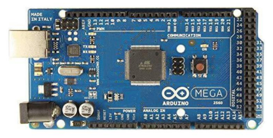
Figure 6. Arduino Mega 2560
(5) Inverse Kinematics of a Three-Joint Leg
The chassis design area is 50cm×51cm, as shown in Figure 7. The maximum allowable weight for the robot is 45 kilograms, but the designed robot frame weighs only 10 kilograms, so aluminum was chosen for the frame material due to its lightweight and high strength. The length from the wheel axis to the center of the robot’s body is 160 mm. Furthermore, the robot is designed for efficient movement and good ball control. Since the robot needs to compete for the ball on the field during soccer matches, its movement must be agile and efficient. The mechanical design of the robot is impact-resistant, lightweight, and difficult to tip over when struck. This three-wheeled omnidirectional robot motion system is triangular, with the omnidirectional wheels mounted at the three vertices.
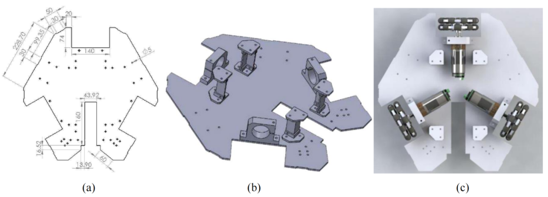
Figure 7. (a) Chassis Mechanical Design; (b) Chassis Mechanical Design View; (c) Wheel Positioning Design
(6) Motion Control System
Motion control is used to monitor the PWM duty cycle, which in turn monitors the speed of each motor, generating the velocity values vx, vy, and ω. The robot’s position can be immediately detected while it moves on a carpeted soccer field.
The motion adjustment block diagram is shown in Figure 8. The speed of the DC motors is obtained in PWM form, and the motion direction of the DC motors includes clockwise (CW) or counterclockwise (CCW). The Arduino Mega 2560 provides PWM values to the EMS 30A-H bridge to drive the PG-45 DC motor.
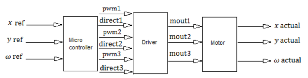
Figure 8. Motion Control Block Diagram
Testing was conducted in a field measuring 2 meters in length and width, with the ground covered in carpet and lines drawn according to the formulas. The specific test directions were as follows:
a. 360°: Move forward;
b. 45°: Move diagonally to the right front;
c. 90°: Move to the right;
d. 135°: Move diagonally to the right back;
e. 180°: Move backward;
f. 225°: Move diagonally to the left back;
g. 270°: Move to the left;
h. 315°: Move diagonally to the left front.
04
Results
(1) Three-Wheeled Omnidirectional Mobile Robot
This study proposes a mobile robot equipped with omnidirectional wheels for the wheeled soccer robot category, as shown in Figure 9. This robot includes a wheel module consisting of three omnidirectional wheels, each connected to a driver. The height of the ground platform is 70 cm, with additional components such as motor drivers, controllers, and batteries installed between the platforms.
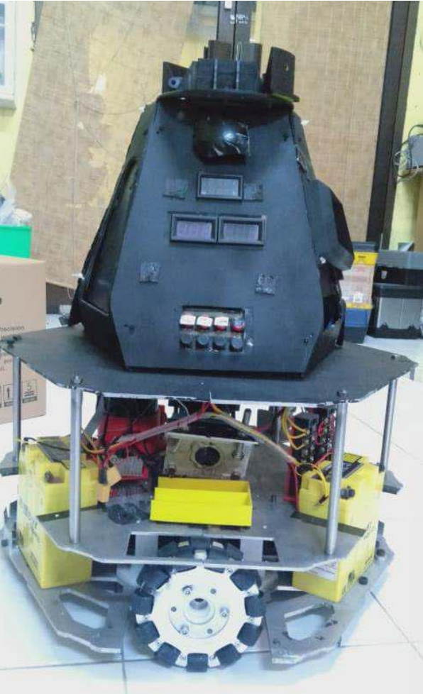
Figure 9. Three-Wheeled Omnidirectional Mobile Robot
(2) Direction Commands
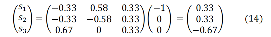
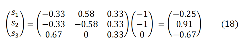
As commands, more information about direction commands can be used in various ways, such as evaluating motor speeds. First, the inverse kinematics formulas (11) to (7) must be used to solve for s1, s2, and s3 to obtain the speed of each wheel.
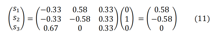
When moving forward, the values of s1, s2, and s3 are (0.58, -0.58, 0).
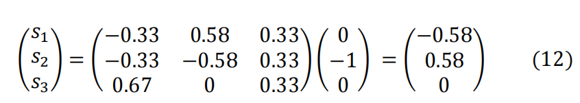
When moving backward, the values of s1, s2, and s3 are (-0.58, 0.58, 0).
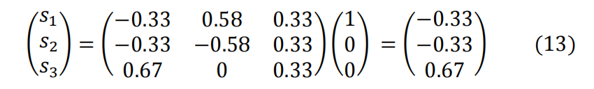
When moving to the right, the values of s1, s2, and s3 are (-0.33, -0.33, 0.67).
When moving to the left, the values of s1, s2, and s3 are (0.33, 0.33, -0.67).
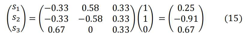
When moving diagonally to the right front, the values of s1, s2, and s3 are (0.25, -0.91, 0.67).
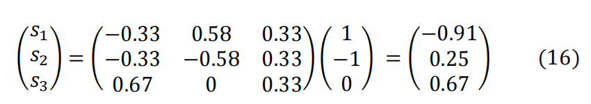
When moving diagonally to the right back, the values of s1, s2, and s3 are (-0.91, 0.25, 0.67).
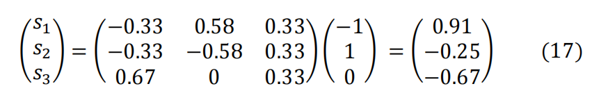
When moving diagonally to the left front, the values of s1, s2, and s3 are (0.91, -0.25, -0.67).
When moving diagonally to the left back, the values of s1, s2, and s3 are (-0.25, 0.91, -0.67).
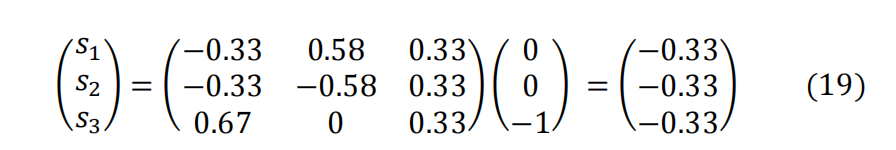
When rotating to the left, the values of s1, s2, and s3 are (-0.33, -0.33, -0.33).
When rotating to the right, the values of s1, s2, and s3 are (0.33, 0.33, 0.33).
(3) Robot Forward Speed Test
To evaluate the relationship between the robot’s forward speed and the PWM input from the microcontroller, a robot speed test was conducted. This test was performed by inputting PWM into the motor driver and adjusting the duty cycle values. The PWM values ranged from 30 to 255 to observe the changes in robot speed over a distance of 2 meters. Table 1 shows the PWM data and the robot’s forward speed.
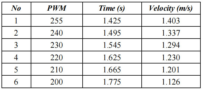
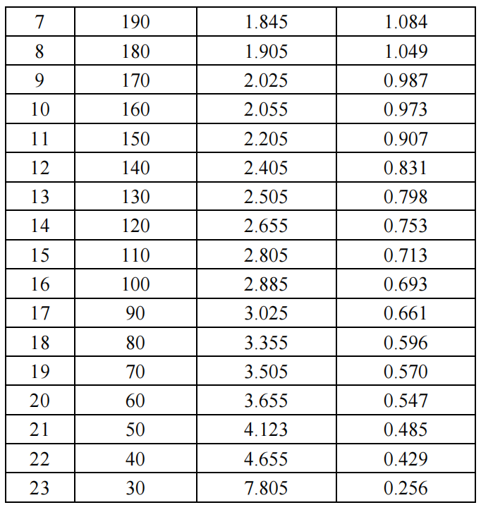
Table 1. Robot Forward Speed
(4) Robot Rotation Angle Test
The purpose of measuring the robot’s rotation angle is to determine its orientation during rotation. This test was conducted by instructing the robot to rotate a specific angle and then observing the actual angle change after the robot’s movement. Table 2 shows the directional angles of the robot’s rotation.
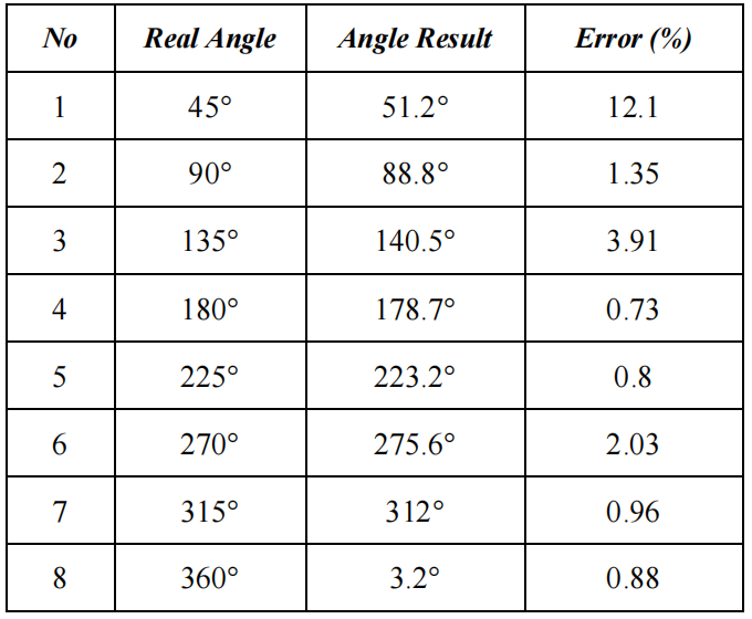
Table 2. Robot Rotation Direction Angles
From this data, it can be determined that the average angular error when the robot moves in the defined direction is 2.84°.
(5) Robot Trajectory Motion Test
The purpose of this test is to determine the actual motion trajectory of the robot and compare it with the results of direct observation in the field. The test was conducted by setting a route connecting the starting point and endpoint, with the system running at a constant speed. The trajectory data was observed, and the actual coordinates were compared with the target coordinates for each trajectory. As shown in Figures 10 to 14, the results of each test are presented in the form of comparison diagrams between the target coordinates and the trajectories generated during the test.
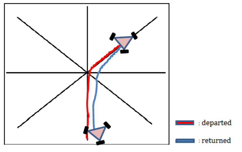
Figure 10. Trajectory 1
Figure 10 shows Trajectory 1, where the observed motion trajectory was forward, diagonally to the right front, diagonally to the left back, backward, and finally stopping.
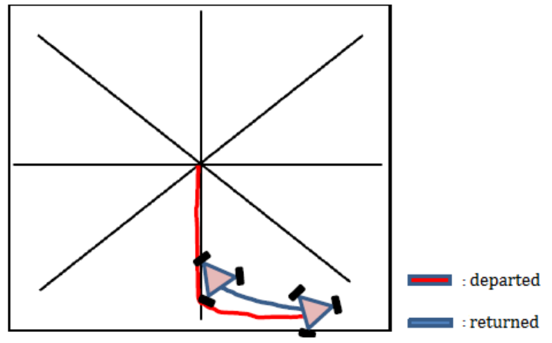
Figure 11. Trajectory 2
Figure 11 shows the robot’s trajectory, first moving backward, then sliding to the right, followed by sliding to the left, then moving forward, and finally stopping.
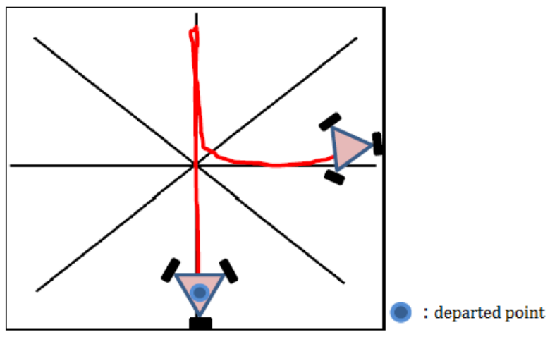
Figure 12. Trajectory 3
The motion trajectory in Figure 12 was forward, backward, to the right, and then stopping.
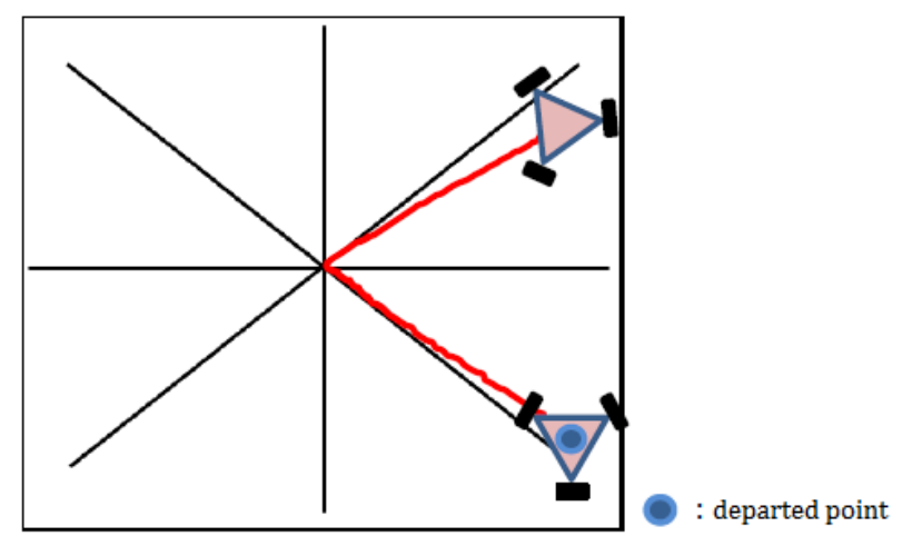
Figure 13. Trajectory 4
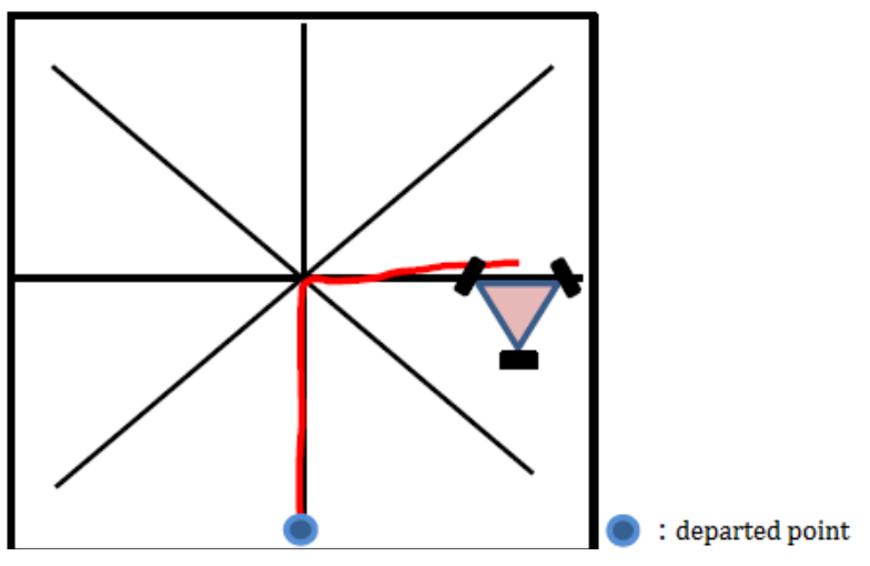
Figure 14. Trajectory 5
From Figures 13 and 14, it can be seen that the robot only performed the starting action. However, in these two figures, the robot only performed two types of movements. Figure 13 shows diagonal movements to the left front and right front, while Figure 14 shows forward movement and sliding to the right, then stopping. In Trajectory 4, the robot changed direction but did not stop on the reference line. In Trajectory 5, the robot stopped with the same direction, but the midpoint of the robot was not on the reference line.
By observing the robot’s five movements, the test trajectory showed speed values ranging from 0.256 m/s to 1.403 m/s, with a directional error of 2.84%.
05
Conclusion
For omnidirectional mobile robots capable of bidirectional movement, a complete constraint method can be employed. A complete motion system is one that can represent the number of degrees of freedom without needing to understand the mechanical structure. Based on the application of complete constraints and the results of inverse kinematics tests, the actual motion trajectory of the robot within the area can be determined. This study introduced the forward, backward, lateral, and diagonal movements of the mobile robot. Data measurements indicate that the robot’s movement speed ranges from 0.256 m/s to 1.403 m/s, with a directional error of 2.84%. In future developments, an algorithm capable of detecting surrounding objects to prevent collisions could be implemented.
Disclaimer: The views expressed in this article are for sharing and communication purposes only. The copyright and interpretation rights belong to the original authors and publishing units. If there are any copyright issues, please contact [email protected], and we will address them promptly.
Related Articles ·
▷ TOP 5 List: The Five Major Generative AI Tools of 2025
▷ The Development History of Quadrupedal Walking Robots and Various Design and Development Methods
▷ Infineon’s Vice President: Three Key Features to Bring Edge AI Mainstream by 2025
▷ Robustness of Multimodal Fusion in Robots
▷ World’s First Bidirectional Adaptive Brain-Computer Interface Successfully Developed by a Chinese Team!
▷ Honda’s ASIMO and Humanoid Robot Research
▷ Hardware Design of Bipedal Humanoid Robots: A Technical Review
▷ Mechanical Principles of Humanoid Robots
▷ Methods of Interaction Between Robots and Humans and Multimodal Interface Architecture
▷ AI-Based Human-Machine Collaborative Unit Task and Action Planning Methods
▷ By 2032, the humanoid robot market size will reach $76.97 billion, with a compound annual growth rate of 48.36%