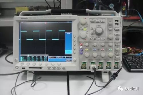

An oscilloscope can observe various electrical signal amplitudes changing over time, and based on this, it can be used to measure parameters such as voltage, time, frequency, phase difference, and modulation depth. Below are the steps for using an oscilloscope to observe electrical signal waveforms.
Depending on the frequency of the signal being measured, set the Y-axis input coupling switch to either AC or DC.
Based on the approximate peak-to-peak value of the signal being measured (if using a probe with attenuation, divide by the attenuation factor; when using DC coupling, also consider the superimposed DC voltage value), set the Y-axis sensitivity V/div switch (or Y-axis attenuation switch) to the appropriate level. In practical use, if there is no need to read the voltage value, you can adjust the Y-axis sensitivity fine-tuning (or Y-axis gain) knob to display the required height of the waveform on the screen.
Typically, set the trigger (or synchronization) signal polarity switch to either “+” or “-” position.
Based on the approximate value of the signal period (or frequency), set the X-axis scan speed t/div (or scan range) switch to the appropriate level. In practical use, if there is no need to read the time value, you can adjust the scan speed t/div fine-tuning (or scan fine-tuning) knob to display the number of cycles required for testing on the screen. If you need to observe the edge portion of the signal, the scan speed t/div switch should be set to the fastest scan speed.
Source: Sui Cha – CNC Alarm
The Leader Said
You click one
The Editor’s Salary Increases by 50 Cents!
WeChat: MW1950MT Article Submission: tougao.mw1950.cn
Recent Encouraged Submission Content: Related to Industrial Robots
Produced by “Metal Processing” (All other submission addresses are false information)
Popular Book Rankings
☞ Gold Powder’s Favorite Book Rankings
☞ Mechanical Processing Rankings
☞ Production Management Rankings
☞ Design Software Rankings
☞ Latest Releases

