01.
LTDC
As we know, the STM32H series, being high-performance chips, mostly comes with peripherals dedicated to LCD screens. Among them, LTDC is the specific peripheral for controlling LCD screens.
LTDC stands for Lcd-Tft Display Controller, which is the LCD refresh controller, available on many H7 series and some other series.
In this issue, we will take STM32N6 as an example to introduce how to use the LTDC peripheral in STM32.
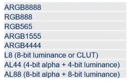
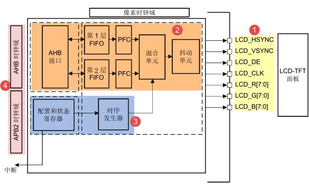
LTDC supports various image color formats, which are unified to RGB format and output to the LCD display through LTDC’s dithering unit.
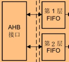
LTDC supports dual-layer blending, allowing us to set the content and transparency of the two layers separately, offering very high display performance and control.
02.
Communication Protocol
Before understanding LTDC, it’s essential to know about the relevant LTDC protocol.
The LTDC protocol is relatively complex compared to basic protocols, and I will only provide a brief introduction. Let’s take a closer look.
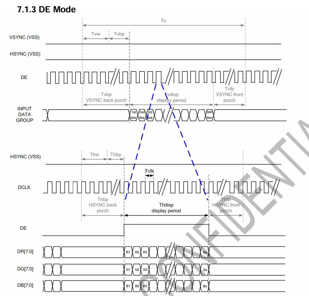
The LTDC protocol is mainly divided into four parts: Synchronization Signals
VSYNC (VSS): Vertical Synchronization Signal
HSYNC (HSS): Horizontal Synchronization Signal
DE: Data Enable Signal
DCLK: Pixel Clock
Data Signals
DR[7:0]: Red Data Line
DG[7:0]: Green Data Line
DB[7:0]: Blue Data Line
Vertical Timing
Tv: Total Time of One Frame
Tvw: VSYNC Pulse Width
Tvbp: VSYNC Back Porch
Tvfp: VSYNC Front Porch
Vdisp: Vertical Display Period
Horizontal Timing
Thw: HSYNC Pulse Width
Thbp: HSYNC Back Porch
Thfp: HSYNC Front Porch
Thdisp: Horizontal Display Period
It is important to note that these parameters vary among different LCDs, and it is necessary to consult the chip manual thoroughly, as there can be significant differences in parameters between different LCDs.
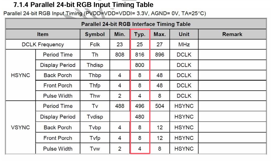
The reference manual provides a typical value, which is clock-based. This table is crucial for using LTDC in STM32 later!
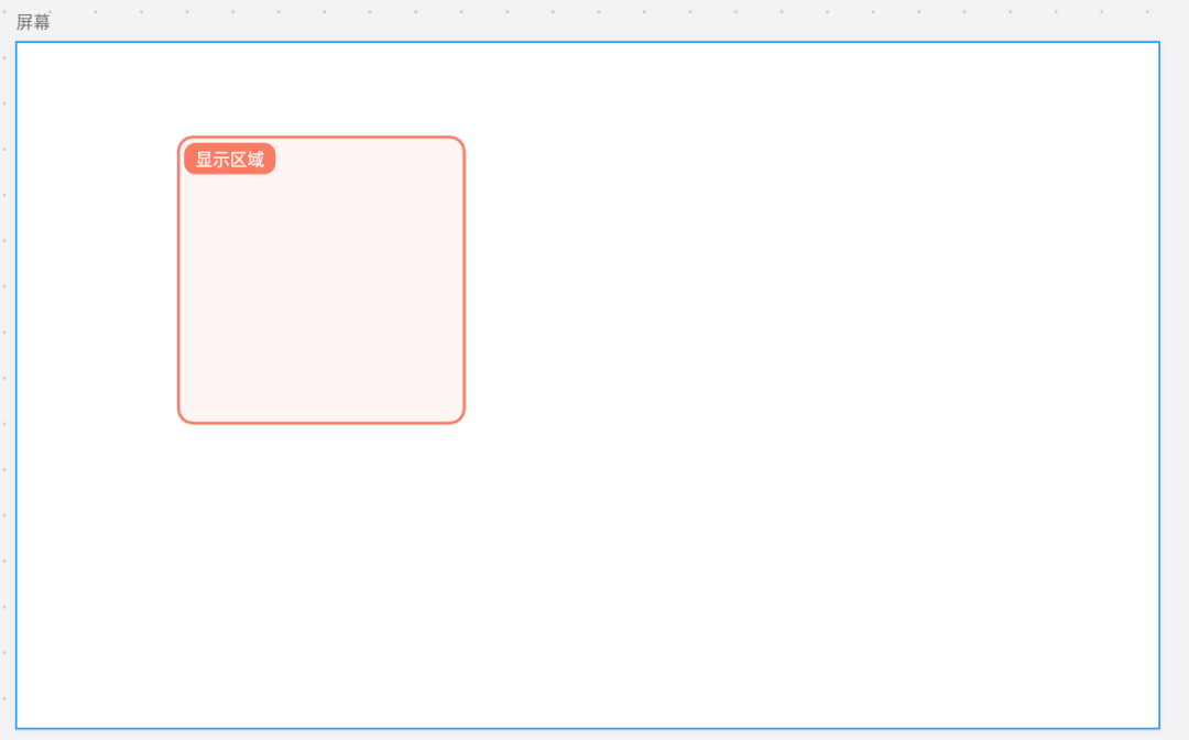
The display area and screen of LTDC are different, and can be decided by us, which is also determined by the Layout layer. Additionally, we can easily control its transparency, background color, and other parameters.
In summary, LTDC is a very flexible and convenient LCD controller.
03.
CubeMX
Taking STM32N6 as an example, we open CubeMX to check the LTDC options.
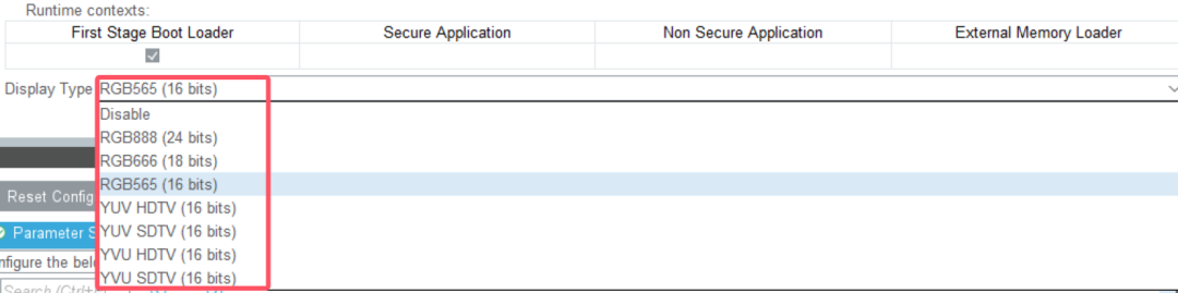
Since our display is RGB888, we set the display refresh mode to RGB888.
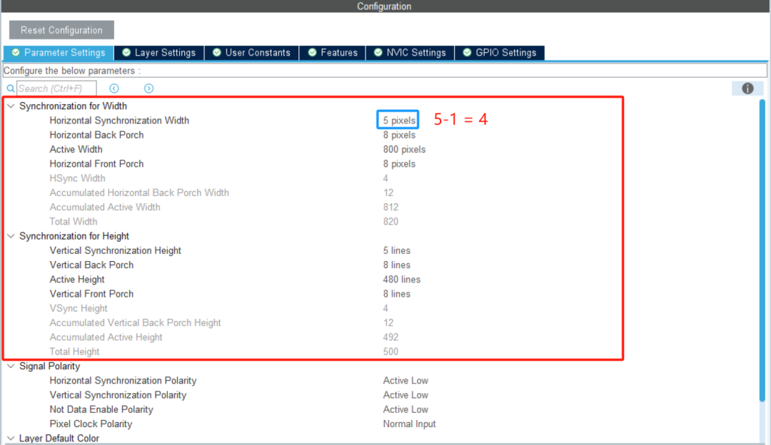
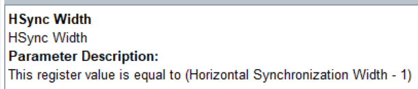
In the parameter settings, input parameters according to the LCD screen manual. Set HSYNC Width to 5, which is the reference number +1, as required. Therefore, when set to 5, the actual application is 4.
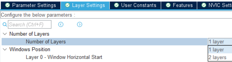
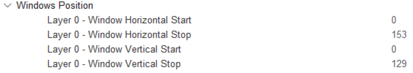
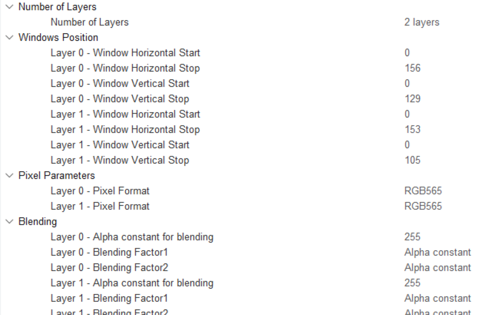
Set the number of layers and the starting position of the window.
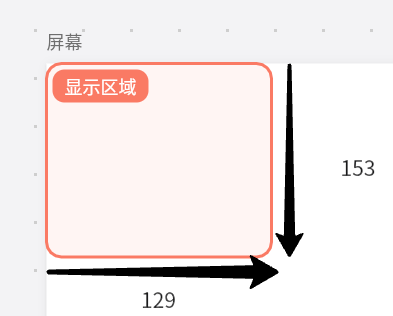
This completes the area setup.
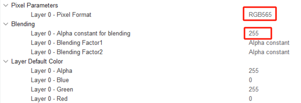
Set the data format of the frame buffer and the default transparency. We set it to fully opaque.
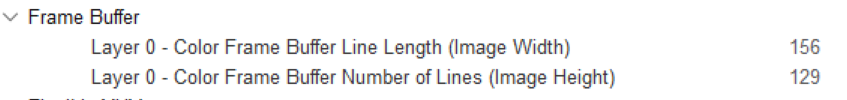
Finally, set the frame buffer size to match the display window size.
Note that some models require entering the address of the frame buffer here, which is the address where we want to display the content. However, N6 does not have an address option, and we need to modify it in the code.
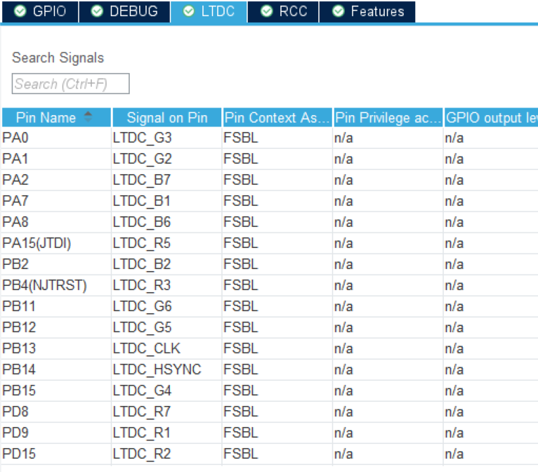
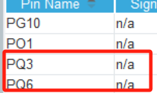
Next, we also need to check if the GPIO pins correspond to the actual pins of the LCD and turn on two IOs to control the LCD’s on/off.
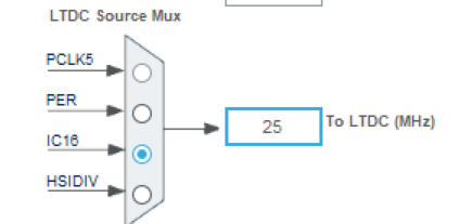
Finally, the LTDC clock must be set. Based on the typical value of 25MHz from the chip manual, we need to pull out a 25MHz clock from the clock tree.
Code Implementation
04.
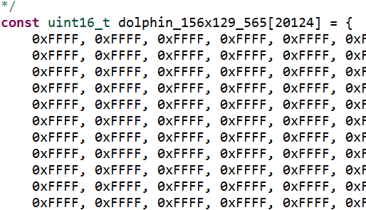
We need image data, here using ST’s example, an image of 156X129 with RGB565 data.
HAL_LTDC_SetAddress(&hltdc, (uint32_t) dolphin_156x129_565, 0);Set the LTDC address, with parameters being the ltdc handle, image address, and layer index.
This allows the image to be displayed properly.
static int i = 255; i = i-5; if(i < 0) { i = 255; } HAL_LTDC_SetAlpha(&hltdc, i, 0);We simply write a function to gradually fade layer 0, decreasing its transparency.
Additionally, we can add another layer to achieve the blending of two images.
HAL_LTDC_SetAddress(&hltdc, (uint32_t) dolphin_156x129_565, 0); HAL_LTDC_SetAddress(&hltdc, (uint32_t) gImage_123, 1); while (1) { static int i = 255; i = i-5; if(i < 0) { i = 255; } HAL_LTDC_SetAlpha(&hltdc, i, 0); HAL_LTDC_SetAlpha(&hltdc, 255-i, 1); HAL_Delay(50); }CubeMX Bug?
05.
Of course, I haven’t used the H7 LTDC yet, as I directly started with N6. However, there was something I discovered during the process.
N6 has a RIF security management mechanism. When referencing ST examples, I found that to use LTDC correctly, it is necessary to set its security. The example code is as follows:
RIMC_master.MasterCID = RIF_CID_1;RIMC_master.SecPriv = RIF_ATTRIBUTE_SEC | RIF_ATTRIBUTE_PRIV;HAL_RIF_RIMC_ConfigMasterAttributes(RIF_MASTER_INDEX_LTDC1 , &RIMC_master);HAL_RIF_RISC_SetSlaveSecureAttributes(RIF_RISC_PERIPH_INDEX_LTDCL1 , RIF_ATTRIBUTE_SEC | RIF_ATTRIBUTE_PRIV);Basically, this assigns a higher security priority to the LTDC layer; otherwise, it seems unable to access the image data.
If you want to use layer 2, you must also increase the priority of LTDC2. However, the issue is that to use these RIMC functions, RIF management needs to be enabled.
However, through layers of investigation, I found that the problem lies in a certain macro definition:
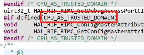
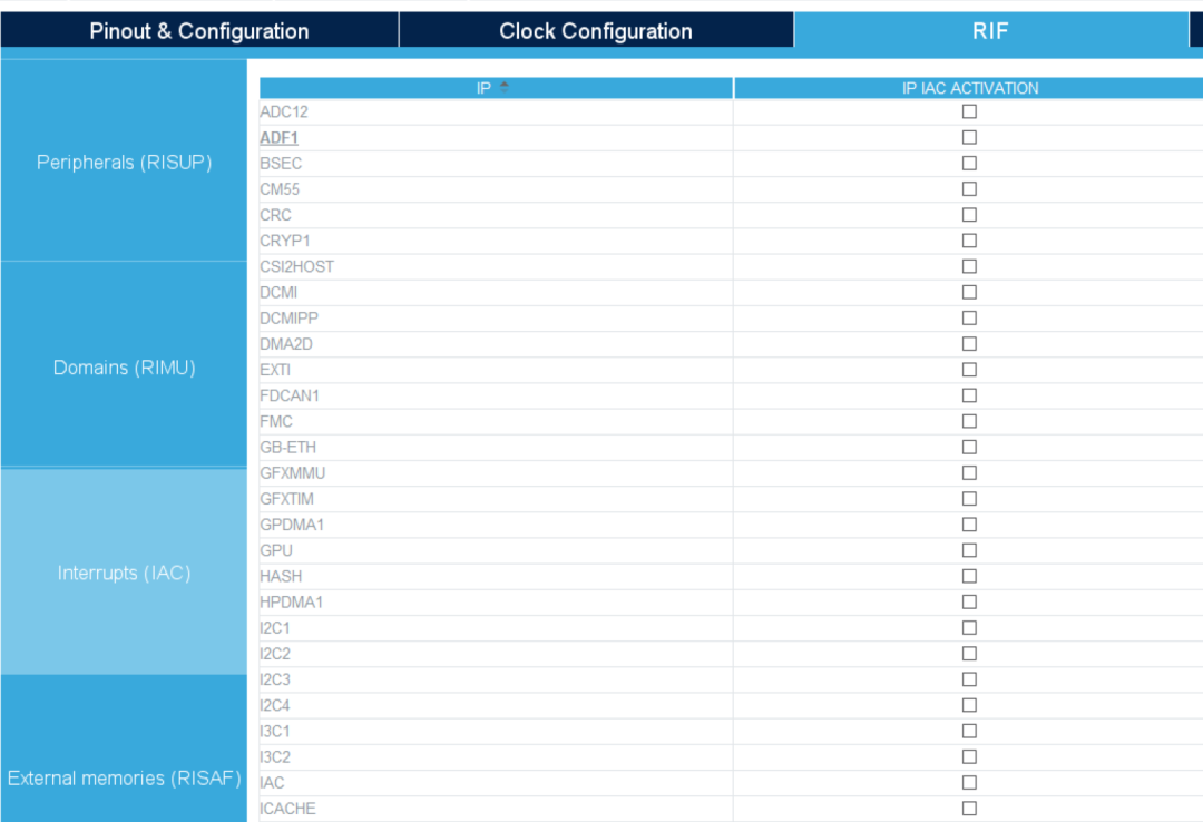
To let the CPU be in a secure domain, I searched for this option for a long time but couldn’t find it. Finally, I had a sudden realization and searched for RIF directly in CubeMX.
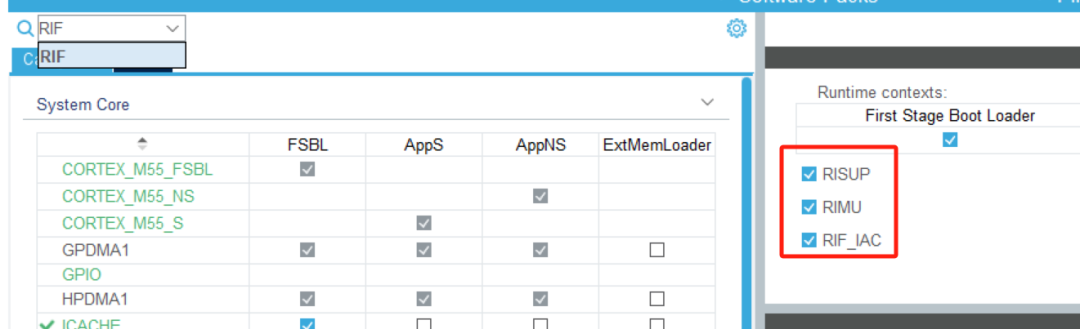
At this point, the RIF configuration will pop up, and you can check the options accordingly.
This shows that sometimes relying too much on CubeMX can lead to issues. However, without CubeMX, figuring this out on your own could take a long time. With CubeMX, I figured it out in one night, so we learn as we go.