Partners engaged in embedded development may have pondered a question: we generally use the driver libraries and initialization files provided by chip manufacturers and start writing programs directly from the main function. So, how does the program guide itself to execute from the main function after the system is powered on? Also, after the system is powered on, the data in RAM is random; how are the initial values of global variables defined?
In the following, I will address these two questions using the Cortex-M architecture as an example, employing IAR EWARM as the compilation toolchain, starting from the first line of code executed after the system is powered on, to outline the system startup process and understand the work done by the compiler during this period. Other toolchains, such as Keil and GCC, perform similar tasks in the system initialization process, but the specific implementations may differ.
1. Startup File
The startup file provided by the chip manufacturer is generally written in assembly language, with a few in C language. The startup file typically contains at least the following two parts:
1. Vector Table
2. Default Interrupt and Exception Handlers
The vector table is essentially an array located at the zero address of memory, where each element stores the entry address of each interrupt or exception handler. Taking the startup file for the STM32F107 chip based on the IAR tool as an example:
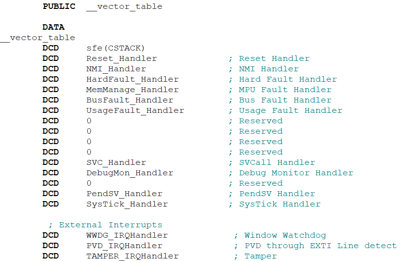
The beginning of the file defines a global symbol named __vector_table, where “DATA” serves to define a data area in the code segment for the vector table. The contents of the data area are defined as 32-bit wide constants using the DCD instruction, except for the first sfe(CSTACK), which is somewhat special; the other constants are the addresses of the exception and interrupt service routines (the function names will be replaced by the entry addresses during compilation). sfe(CSTACK) is an IAR assembler segment operation used to obtain the end address of the section, but what is its intention here?
In fact, this is an operation to obtain the stack base address. IAR defines the stack in the linker script (*.icf) file, essentially defining a free block named “CSTACK”, as shown in the script command below. A block refers to reserving a segment of contiguous address space to be used as a stack or heap. Of course, a block can also contain content, for example, it can be used to manage segments, but that is not the topic of today’s discussion.

We know that the stack model of the Cortex-M architecture is a full decrement stack, where the stack grows from high addresses to low addresses, so the base address of the stack is the end address of CSTACK.
The first element of the vector table is the stack base address, which is defined by the Cortex-M architecture. After the system is powered on, the hardware automatically retrieves it from the vector table and sets the Main Stack Pointer (MSP), unlike other ARM architectures where the stack pointer must be set by software.
The second element in the vector table is the entry address of the reset exception (Reset_Handler). After the system is powered on, the hardware automatically reads from the __vector_table + 4 position and begins execution from the retrieved address. The first instruction executed by the CPU after powering on the system is the first statement of the Reset_Handler function.
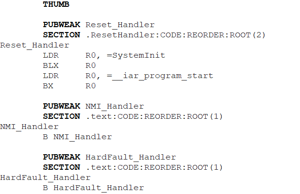
The THUMB command above indicates that the following code uses THUMB mode (Cortex-M only supports the Thumb-2 instruction set); SECTION is used to define a section, named “.ResetHandler”, with a type of code (CODE); REORDER indicates that a new section is opened with the given name; ROOT indicates that the linker should not discard this section even if the symbols within the section are not referenced.
PUBWEAK is a weak definition; if the user writes an interrupt handler elsewhere, the linker will link the user-written one, ignoring the service function written in assembly in the startup file. The reason for writing all exception and interrupt service functions in the startup file as weak definitions is to prevent the user from enabling and triggering interrupts without writing service functions, leading to system uncertainty.
2. System Initialization Process
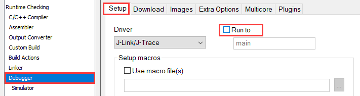
In the EWARM project Options > Debugger > Setup, uncheck “Run to” so that it will stop at the first line of code to be executed when entering debugging:
Upon entering debugging, it will stop at the first assembly instruction of the Reset_Handler function in the startup file:
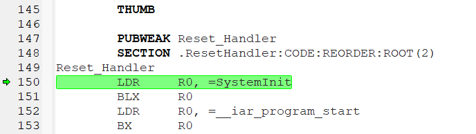
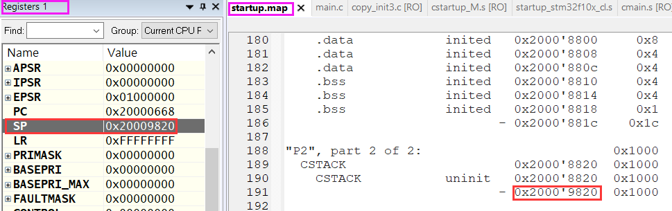
At this point, by observing the register view, the value of SP is 0x20009820. By checking the address range of CSTACK generated during linking, 0x20009820 is exactly the end address of CSTACK. With the MSP, C code can run.
The SystemInit function is a basic configuration function provided by the chip manufacturer according to the ARM CMSIS standard, which configures the basic clock system and vector table relocation, etc. Here, LDR is a pseudo-instruction that loads the address of the SystemInit function into register R0, which is actually obtained through PC-relative addressing.

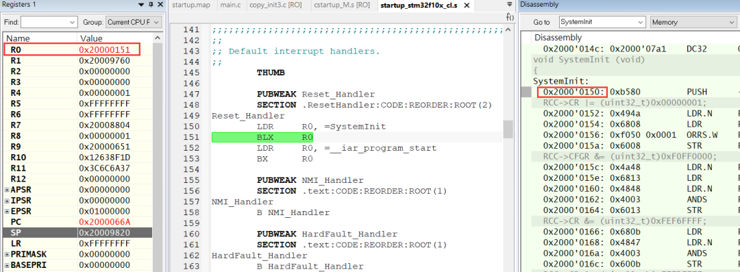
From the above figure, we can observe a problem: in the disassembly window, the address of SystemInit is 0x20000150, but after loading it into register R0, it is 0x20000151. This is because when using the jump instruction to update the PC, the LSB of the PC needs to be set to 1 to indicate THUMB mode. Since Cortex-M does not support ARM mode, the LSB is always 1.
After executing the SystemInit function provided by the chip manufacturer, it jumps to __iar_program_start, which is the entry point of the initialization code provided by the IAR compiler.
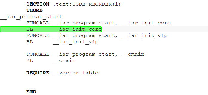
__iar_program_start will first execute two functions: __iar_init_core and __iar_init_vfp, which perform some CPU and FPU related initialization operations. In some ARM architectures, the packaged runtime library will have these two functions, and users can also rewrite these functions to implement related operations themselves.
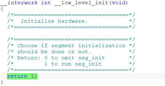
After that, it jumps to the __cmain function for execution. In __cmain, a __low_level_init function is called, which is specifically provided for users to write a basic initialization operation. It executes before global variable initialization, for example, it can be used to initialize SDRAM in __low_level_init, allowing global variables to be defined in SDRAM for use.
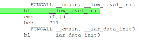
__low_level_init can be written in any C file, but pay attention to its return value. If it returns 0, the subsequent variable initialization operation will be skipped; normally it returns 1.
3. Initialization of Global Variables
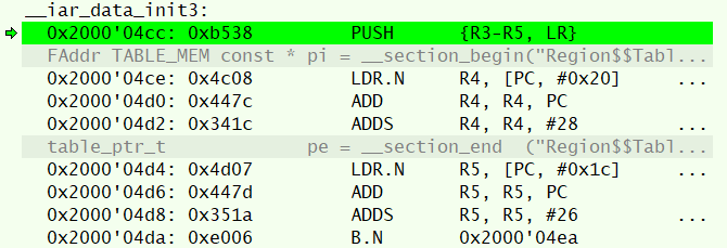
Subsequently, it enters the __iar_data_init3 function, where all global/static variables with initial values are assigned, and global/static variables are zero-initialized. The functions __iar_copy_init3 and __iar_zero_init3 are called to copy the initial values of variables stored in the ROM area generated by the linker to the variable addresses. Note that the new EWARM version may use compression algorithms for variable initialization operations, and the actual function called for variable initialization may differ.
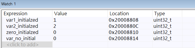
Before the global variables are initialized, the watch window shows that their values are all random numbers.

After the __iar_data_init3 function completes, all initial values of the variables have been assigned.
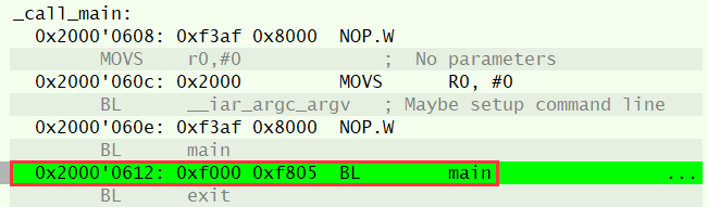
At the end of the __cmain function, it jumps to the user’s main function, and the user’s code execution finally begins.
4. Conclusion
Having understood the initialization process provided by the compiler and the processor architecture, we can customize the system initialization according to our needs. For example, necessary hardware initialization operations can be performed before entering __iar_program_start, which can be written in assembly or C. We can also manually control variable initialization operations and implement our own variable initialization. Moreover, it is even possible to completely bypass the initialization operations provided by the IAR compiler and guide directly from the reset sequence to the main function.