Digital Multimeter
The digital multimeter is relatively simple measurement equipment. In this article, the author will teach you the correct usage of a digital multimeter. Starting with measurement methods for voltage, resistance, current, diodes, transistors, and MOSFETs, you will better master the multimeter measurement techniques.
Tip: Please watch the video in a WiFi environment~
1. Measuring Voltage
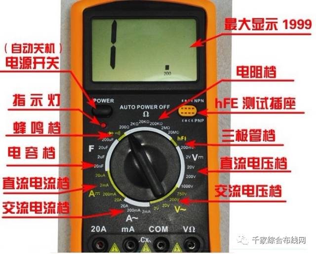
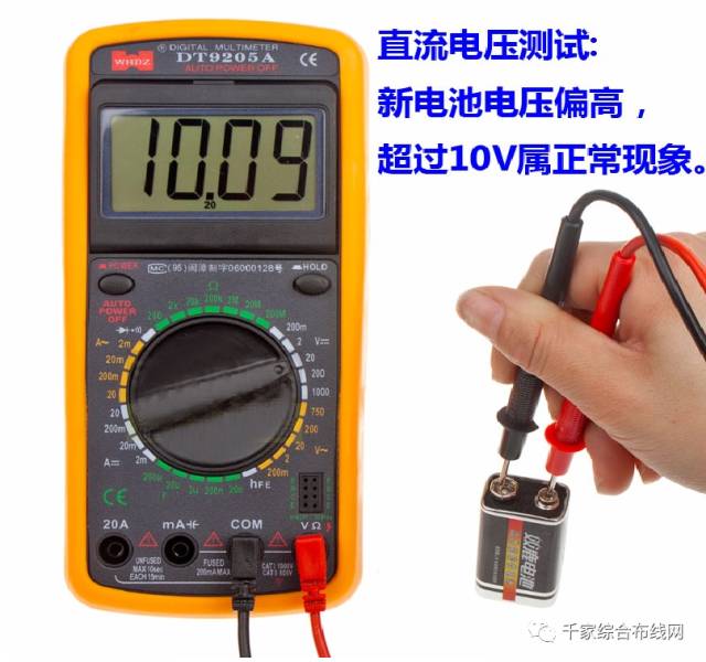
1. Measuring DC voltage, such as batteries, portable audio device power sources, etc. First, insert the black probe into the “com” hole and the red probe into the “V Ω” hole. Turn the knob to a range larger than the estimated value (Note: The values on the dial are all maximum ranges, “V-” indicates DC voltage, “V~” indicates AC voltage, and “A” is the current range). Then connect the probes to both ends of the power source or battery; maintain stable contact. The value can be read directly from the display. If it shows “1.”, it indicates the range is too small, so increase the range and measure the industrial equipment again. If a “-” appears on the left side of the value, it indicates that the probe polarity is opposite to the actual power polarity, meaning the red probe is connected to the negative terminal.
2. Measuring AC voltage. The probe socket is the same as for DC voltage measurement, but the knob should be set to the AC range “V~”. There is no positive or negative for AC voltage; the measurement method is the same as before. Whether measuring AC or DC voltage, always pay attention to personal safety and do not touch the metal parts of the probes casually.
2. Measuring Current
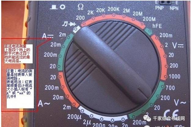
1. Measuring DC current. First, insert the black probe into the “COM” hole. If measuring current greater than 200mA, insert the red probe into the “10A” socket and set the knob to the DC “10A” range; if measuring current less than 200mA, insert the red probe into the “200mA” socket and set the knob to an appropriate range under 200mA. Once adjusted, you can start measuring. Connect the multimeter in series with the circuit, maintain stability, and read the value. If it shows “1.”, you need to increase the range; if a “-” appears on the left side, it indicates that the current is flowing into the multimeter from the black probe.
2. Measuring AC current. The measurement method is the same as for DC current, but the position should be set to the AC range. After measuring the current, remember to return the red probe to the “VΩ” hole; if you forget this step and directly measure voltage, haha! Your multimeter or power source will go up in smoke — it will be scrapped!
3. Measuring Resistance
Insert the probes into the “COM” and “VΩ” holes, turn the knob to the required resistance range “Ω”, and connect the probes to the metal parts at both ends of the resistor. During measurement, you can touch the resistor with your hand, but do not touch both ends of the resistor at the same time, as this will affect measurement accuracy — the human body is a conductor with high but limited resistance. When reading, ensure good contact between the probes and the resistor; note the units: in the “200” range, the unit is “Ω”, in the “2K” to “200K” range, the unit is “KΩ”, and above “2M”, the unit is “MΩ”.
4. Measuring Diodes
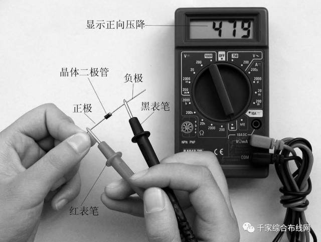
The digital multimeter can measure LEDs, rectifier diodes, etc. For measurement, the probe positions are the same as for voltage measurement, and set the knob to the diode range; connect the red probe to the anode of the diode and the black probe to the cathode. The forward voltage drop of the diode will be displayed. The forward voltage drop for Schottky diodes is around 0.2V, for standard silicon rectifiers (like 1N4000, 1N5400 series) it’s about 0.7V, and for LEDs it’s around 1.8 to 2.3V. If you reverse the probes and the display shows “1.”, it indicates normal operation, as the reverse resistance of the diode is very high; otherwise, the diode has been damaged.
5. Measuring Transistors
Insert the probes as above; the principle is the same as for diodes. First, assume pin A is the base, connect the black probe to this pin, and the red probe to the other two pins respectively; if both readings are around 0.7V, then use the red probe on pin A and the black probe on the other two pins; if both show ‘1’, then pin A is the base; otherwise, you need to measure again, and this is a PNP transistor. How to identify the collector and emitter? A digital meter cannot judge like an analog meter using the pointer swing; what to do? We can use the “hFE” range to determine: switch to the “hFE” range, where you will see a row of small sockets for measuring PNP and NPN transistors. Having determined the type of transistor, insert the base into the corresponding “b” socket, and the other two pins into the “c” and “e” sockets respectively; at this point, you can read the value, which is the β value; then fix the base and switch the other two pins; compare the two readings, and the larger reading corresponds to the “c” and “e” on the surface.
Tip: This method only works for small transistors like the 9000 series; for larger transistors, you can use wiring methods to lead out the three pins. This makes things much easier!
6. Measuring MOSFETs
For N-channel types, there are domestic 3D01, 4D01, and the Japanese 3SK series. To determine the G (gate) pin: use the diode range of the multimeter. If the forward and reverse voltage drops between a pin and the other two pins are both greater than 2V, showing “1”, then that pin is the gate G. Then swap the probes to measure the other two pins, and the smaller voltage drop indicates the black probe is connected to the D (drain) pin and the red probe to the S (source) pin.
1. Voltage range. During testing or production, it can be used to measure the voltage at each pin of the device and compare it with the normal voltage to determine if it is damaged. It can also be used to detect the voltage of zener diodes with a small regulation value, as shown in the figure: R is 1K, and the voltage at the power supply end depends on the nominal regulation value of the zener diode, generally more than 3V above the nominal voltage but not exceeding 15V. Then use the multimeter to measure the voltage across the D diode; this value is the actual regulation value of the D diode.
2. Current range. Connect the meter in series with the circuit to measure and monitor the current; if the current deviates significantly from the normal value (based on experience or existing parameters), necessary adjustments to the circuit or repairs may be needed. You can also use the 20A range of this meter to measure the short-circuit current of a battery by directly connecting the two probes to the battery terminals. Remember, the time should not exceed 1 second!
Note: This method is only suitable for dry batteries, size 5 or 7 rechargeable batteries, and beginners should be guided by someone familiar with repairs; do not operate independently! Based on the short-circuit current, you can judge the performance of the battery; under the same conditions of fully charged batteries, the larger the short-circuit current, the better.
3. Resistance range. This can be one of the methods used to determine the condition of resistors, diodes, and transistors. If the actual resistance value deviates too much from the nominal value, it is considered damaged. For diodes and transistors, if the resistance between any two pins is not a very high value (above several hundred K), it can be considered that the performance has degraded or has been damaged; note that this transistor is not biased. This method can also be used for integrated circuits; it should be noted that the measurement of integrated circuits can only be compared with normal parameters.
4. Nowadays, most ordinary multimeter probes have high resistance values; enthusiasts can make their own set of probes. Method: Prepare a high-quality speaker wire or multi-strand copper wire about a meter long, a pair of insulated clips (red and black), and a pair of banana plugs for speaker connections (red and black); solder one end to the clip and the other end into the corresponding banana plug; a good set of probes is complete.


★ Disclaimer:Some content is compiled from the internet, and the copyright belongs to the author. For copyright issues, please contact us, and we will delete it in the shortest time.
Click the above ↗[●●●] to send to a friend or share to your circle of friends
Click Read Original to get more! If you like this article, please give a thumbs up below!
