This is a supplement to previous content. Earlier, we published an article on measuring breakpoints, and many friends mentioned the use of multimeters. Indeed, we have published relatively little content on the use of multimeters, but they are quite versatile in practical projects. So let’s explore this topic together.
1. What is a Multimeter
Also known as a multimeter, three-function meter, or universal meter, the multimeter is divided into analog multimeters and digital multimeters.
It is a multi-functional, multi-range measuring instrument. Generally, a multimeter can measure DC current, DC voltage, AC voltage, resistance, and audio level, and some can also measure AC current, capacitance, inductance, and certain parameters of semiconductors.
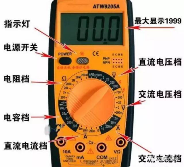
The multimeter consists of three main parts: the display, measurement circuit, and selector switch.

2. Using the Multimeter
1. Familiarize yourself with the meanings of the symbols on the dial and the main functions of each knob and selector switch.
2. Perform mechanical zeroing.
3. Select the appropriate range and position of the selector switch based on the type and size of the measurement, and find the corresponding scale line.
4. Choose the position of the test lead jacks.
5. Measuring Voltage:
Select the appropriate range. If you use a small range to measure a large voltage, there is a risk of burning the meter; if you use a large range to measure a small voltage, the needle will deflect too little to read.
The range selection should ideally make the needle deflect to about 2/3 of the full scale.
If you are unsure of the measured voltage’s size beforehand, first select the highest range and then gradually decrease to an appropriate range.
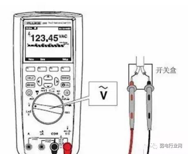
(1) Measuring AC Voltage:
Set one selector switch of the multimeter to the AC/DC voltage position and the other to the appropriate AC voltage range. Connect the two test leads in parallel with the circuit or load being measured.
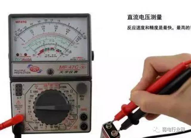
(2) Measuring DC Voltage:
Set one selector switch of the multimeter to the AC/DC voltage position and the other to the appropriate DC voltage range, ensuring the red lead is connected to the high potential and the black lead to the low potential, allowing current to flow into the red lead and out of the black lead. If the leads are connected in reverse, the pointer will deflect in the opposite direction, which can bend the pointer.
6. Measuring Current:
(1) When measuring DC current, set one selector switch of the multimeter to the DC current position and the other to the appropriate range between 50uA and 500mA. The current range selection and reading method are the same as for voltage.
(2) You must first disconnect the circuit and then connect the multimeter in series with the circuit being measured, allowing current to flow from the red lead to the black lead.
If you mistakenly connect the multimeter in parallel with the load, the internal resistance of the meter is very low, which may cause a short circuit and damage the instrument.
(3) Reading Method: Actual value = Indicated value × Range / Full scale deflection.
7. Measuring Resistance:
When measuring resistance with a multimeter, follow these methods:
(1) Select the appropriate range.
The scale lines on the ohm range of the multimeter are not uniform, so the range selection should keep the pointer in the less dense part of the scale, and the closer the pointer is to the middle of the scale, the more accurate the reading. Generally, the pointer should be between 1/3 and 2/3 of the scale.
(2) Ohm Zeroing.
Before measuring resistance, short the two test leads and adjust the “ohm (electric) zeroing knob” so that the pointer just points to the zero position on the ohm scale.
If the pointer cannot be adjusted to the zero position, it indicates insufficient battery voltage or an internal problem with the instrument. Additionally, every time you change the range, you must perform ohm zeroing again to ensure accurate measurements.
(3) Reading:
The reading on the display multiplied by the range gives the resistance value being measured.
8. Measuring Three-Phase Voltage
Three-phase electricity means that the voltage between three phase wires is 380V, and the voltage between any two phase wires is also 380V, known as line voltage 380V; 220V is the voltage between any one phase wire and the neutral wire.
When measuring three-phase voltage and household voltage with a multimeter, the voltage between any two of A, B, and C is AC 380V, that is, A-B, B-C, C-A are all 380V;
Any one of A, B, and C with N has a voltage of 220V, that is, A-N, B-N, C-N are all 220V.

3. Tips for Using a Multimeter
Proper use of a multimeter can not only quickly and accurately identify the fault location but also prevent damage to electrical equipment and the multimeter itself. Let’s first look at themultimeter usage guidelines:
1. Check the range before measuring; don’t measure without checking.
Whenever you pick up the test leads to prepare for measurement, be sure to double-check whether the measurement category and range selection switch are set correctly. For safety, you must develop this habit.
You should not arbitrarily turn the selection knob during measurement, especially when measuring high voltage (e.g., 220V) or large current (e.g., 0.5A), to avoid generating an arc that could damage the contacts of the selector switch. After measuring, set the range selection switch to the “•” position.
3. The dial should be level, and readings should be aligned.
When using a multimeter, it should be rotated horizontally, and your line of sight should be aligned with the pointer when reading.
4. The range should be appropriate, with the needle deflected more than half.
When selecting the range, if you cannot estimate the size of the measurement beforehand, try to select a larger range first, and then gradually switch to a smaller range based on the deflection angle until the pointer deflects to about 2/3 of the full scale.
It is strictly forbidden to measure resistance while the circuit is powered. When checking large capacitors in electrical equipment, discharge the capacitor before measuring.
When measuring resistance, first set the selector switch to the resistance range, short the two test leads, and adjust the “Ω” zeroing potentiometer so that the pointer points to zero ohm before measuring. Every time you change the resistance range, you should readjust the ohm zero point.
7. Remember that black is negative, the black lead connects to the positive inside the meter.
The red lead is positive, and the black lead is negative, but in the resistance range, the black lead connects to the positive terminal of the internal battery.
8. Measure current in series; measure voltage in parallel.
When measuring current, the multimeter should be connected in series with the circuit being measured; when measuring voltage, the multimeter should be connected in parallel across the two ends of the circuit being measured.
When measuring current and voltage, pay special attention to ensure the red and black leads are not connected in reverse, and always develop a one-handed operation habit for safety.
The above is a detailed guide on the use of multimeters. Finally, we will summarize through a video tutorial to see the specific techniques for using a multimeter.

Latest weak current data update—Weak current quotation No. 451 (April 21)