1. Basic Working Principles of Multimeters
“Multimeter” is short for multimeter, which is an essential tool in our electronic production. Multimeters can measure current, voltage, resistance, and some can also measure transistor amplification, frequency, capacitance, logic levels, and decibel values. There are many types of multimeters, with the most popular being analog and digital multimeters. Each has its advantages and disadvantages; for beginners in electronics, it is recommended to use an analog multimeter as it helps us understand some electronic principles better. Below, we mainly introduce the measuring principles of the analog multimeter.
The basic principle of this type of multimeter is to use a sensitive magnetic electrodynamic DC ammeter (microammeter) as the meter head. When a small current passes through the meter head, there will be a current indication. However, the meter head cannot handle large currents; therefore, it is necessary to parallel and series some resistors on the meter head to divert or reduce the voltage, thereby measuring the current, voltage, and resistance in the circuit. Below, we will introduce them respectively.
1. Measuring DC Current Principle.
As shown in Figure 1a, by parallel connecting an appropriate resistor (called a shunt resistor) on the meter head for diversion, the current range can be extended. By changing the resistance value of the shunt resistor, the current measurement range can be changed.
2. Measuring DC Voltage Principle.
As shown in Figure 1b, by connecting an appropriate resistor (called a multiplier resistor) in series with the meter head for voltage reduction, the voltage range can be extended. By changing the resistance value of the multiplier resistor, the voltage measurement range can be changed.
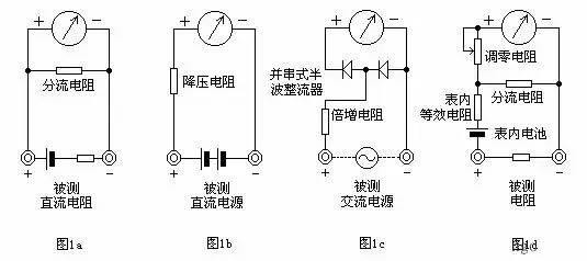
3. Measuring AC Voltage Principle.
As shown in Figure 1c, since the meter head is a DC meter, when measuring AC, a half-wave rectifier circuit must be added in parallel and in series to convert AC to DC before passing through the meter head. This way, the AC voltage can be measured based on the size of the DC current. The method for extending the AC voltage range is similar to that for DC voltage.
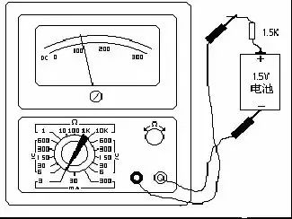
4. Measuring Resistance Principle.
As shown in Figure 1d, by parallel and series connecting appropriate resistors on the meter head and connecting a battery in series, current flows through the resistance being measured, and the resistance value can be measured based on the size of the current. By changing the resistance value of the shunt resistor, the resistance measurement range can be changed.
2. Usage of Multimeters
The dial of the multimeter (taking the 105 model as an example) is shown in the right image. The measurement item and range can be changed by rotating the switch knob. The mechanical zero adjustment knob is used to keep the pointer at the left zero position when still. The “Ω” zero adjustment knob is used to align the pointer to the right zero position when measuring resistance to ensure accurate measurement values.
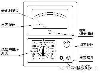
The measurement ranges of the multimeter are as follows:
DC Voltage: 5 ranges—0-6V; 0-30V; 0-150V; 0-300V; 0-600V.
AC Voltage: 5 ranges—0-6V; 0-30V; 0-150V; 0-300V; 0-600V
DC Current: 3 ranges—0-3mA; 0-30mA; 0-300mA.
Resistance: 5 ranges—R*1; R*10; R*100; R*1K; R*10K
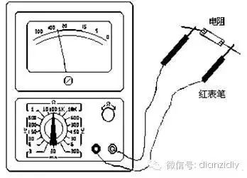
Measuring Resistance: — First, short the test leads together to make the pointer deflect to the right, then adjust the “Ω” zero knob to make the pointer point exactly to 0. Then connect the two test leads to both ends of the resistance (or circuit) being measured, read the pointer’s position on the ohm scale (the first line), and multiply by the number marked on that range to get the measured resistance value. For example, if measuring resistance with the R*100 range and the pointer points at 80, the measured resistance value is 80*100=8K. Since the left part of the “Ω” scale has dense readings, it is difficult to pinpoint, so choose an appropriate ohm range during measurement. This allows the pointer to be in the middle or right part of the scale, making the reading clearer and more accurate. Each time you change the range, you should short the two test leads again and adjust the pointer back to zero to ensure accurate measurement.
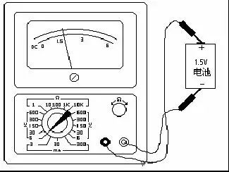
Measuring DC Voltage: — First estimate the size of the voltage being measured, then turn the switch to the appropriate V range, connect the positive test lead to the “+” end of the voltage being measured, and connect the negative test lead to the “-” end. Then read the measured voltage based on the pointer’s position on the range number and the marked DC symbol “DC-” scale (the second line). For example, if measuring with the V300 range, you can directly read the indicated value from 0-300. If measuring with the V30 range, simply remove one “0” from the scale number 300, consider it as 30, and read the pointer’s indicated value as 20, 10, etc. For example, if measuring DC voltage with the V6 range and the pointer points at 15, the measured voltage is 1.5 volts.
Measuring DC Current: — First estimate the size of the current being measured, then turn the switch to the appropriate mA range, and connect the multimeter in series in the circuit as shown. At the same time, observe the scale marked with the DC symbol “DC”; if the current range is set to the 3mA range, the scale number 300 should have two “0”s removed, seen as 3, and the numbers 200 and 100 should be seen as 2 and 1, respectively, allowing you to read the measured current value. For instance, if measuring DC current with the 3mA range and the pointer is at 100, the current is 1mA.
Measuring AC Voltage: — The method for measuring AC voltage is similar to measuring DC voltage, except that AC does not have positive and negative distinctions, so when measuring AC, the test leads do not need to be distinguished as positive or negative. The reading method is the same as that for measuring DC voltage, but the numbers should be read from the scale marked with the AC symbol “AC”.
3. Precautions When Using a Multimeter
The multimeter is a relatively precise instrument; improper use can not only lead to inaccurate measurements but also easily damage the device. However, as long as we master the usage methods and precautions of the multimeter and proceed cautiously, the multimeter can be durable. When using a multimeter, the following precautions should be noted:
1) Do not rotate the switch to the wrong position when measuring current and voltage. If you mistakenly select the resistance range or current range to measure voltage, it can easily burn out the multimeter. When not in use, it is best to turn the range to the highest AC voltage to avoid damage due to improper use.
2) When measuring DC voltage and DC current, pay attention to the “+” and “-” polarity; do not connect them incorrectly. If the pointer reverses, immediately switch the test leads to avoid damaging the pointer and meter head.
3) If you do not know the size of the voltage or current being measured, you should first use the highest range and then select an appropriate range to test to avoid excessive deflection of the pointer, which could damage the meter head. The closer the selected range is to the measured value, the more accurate the measurement will be.
4) When measuring resistance, do not touch the bare ends of the components (or the metal parts of the two test leads) to avoid the human body resistance being in parallel with the measured resistance, which can lead to inaccurate measurement results.
5) When measuring resistance, if the two test leads are shorted and the “zero ohm” knob is adjusted to the maximum, and the pointer still does not reach 0, this phenomenon is usually caused by insufficient battery voltage inside the meter; a new battery should be replaced for accurate measurement.
6) When not in use, do not leave the switch on the resistance range, as there is a battery inside. If not careful, the two test leads may short-circuit, which not only drains the battery but can also seriously damage the meter head.
4. Tips for Using a Multimeter
1. Choosing Between Analog and Digital Meters:
1) The reading accuracy of analog meters is relatively poor, but the process of the pointer swinging is more intuitive, and its swing speed and amplitude can sometimes objectively reflect the size of the measured value (for example, measuring the slight jitter of the data bus (SDL) in a television during data transmission); digital meters provide intuitive readings, but the changing digits appear chaotic and are not easy to read.
2) Analog meters generally have two batteries, one low voltage 1.5V and one high voltage 9V or 15V, with the black probe being positive relative to the red probe. Digital meters typically use a single 6V or 9V battery. In the resistance range, the output current of the analog meter’s probes is much larger than that of the digital meter; using the R×1Ω range can make the speaker emit a loud “click” sound, and using the R×10kΩ range can even light up a light-emitting diode (LED).
3) In the voltage range, the internal resistance of the analog meter is relatively low compared to the digital meter, resulting in lower measurement accuracy. In certain high voltage and microcurrent situations, it may even be impossible to measure accurately, as its internal resistance can affect the circuit being measured (for example, when measuring the accelerating voltage of a television’s cathode ray tube, the measured value will be much lower than the actual value). The voltage range of the digital meter has a very high internal resistance, at least in the megaohm range, which has little effect on the circuit being measured. However, the very high output resistance makes it susceptible to induced voltage, and in some environments with strong electromagnetic interference, the data measured may be false.
4) In summary, in relatively high current and high voltage analog circuit measurements, analog meters are suitable, such as televisions and audio amplifiers. For low voltage and low current digital circuit measurements, digital meters are suitable, such as pagers and mobile phones. It is not absolute and can be selected based on the situation.
2. Measurement Techniques (if not specified, it refers to the use of an analog meter):
1) Measuring speakers, headphones, and dynamic microphones: Use the R×1Ω range; connect one probe to one end and touch the other probe to the other end. Normally, a crisp “click” sound will be produced. If there is no sound, it indicates a broken coil; if the sound is small and sharp, it indicates a rubbing issue, which is also not usable.
2) Measuring capacitance: Use the resistance range, select an appropriate range based on the capacitance size, and note that for electrolytic capacitors, the black probe should connect to the positive terminal. ① Estimate the size of microwave-level capacitors: you can determine it based on experience or by referencing standard capacitors of the same capacity, judging by the maximum swing of the pointer. The referenced capacitor does not need to have the same voltage rating, as long as the capacitance is the same. For example, to estimate a 100μF/250V capacitor, you can use a 100μF/25V capacitor as a reference, as long as their pointer swings have the same maximum amplitude, it can be concluded that the capacitance is the same. ② To estimate the size of picofarad-level capacitors: use the R×10kΩ range, but it can only measure capacitors above 1000pF. For capacitors around 1000pF or slightly larger, as long as the pointer swings slightly, it can be considered sufficient. ③ To check if a capacitor is leaking: for capacitors above 1000μF, first use the R×10Ω range to quickly charge it and initially estimate the capacitance, then switch to the R×1kΩ range and continue measuring for a while. At this point, the pointer should not return but should stop at or very close to ∞; otherwise, there is a leakage issue. For timing or oscillating capacitors below several tens of microfarads (such as the oscillating capacitor of a color television switch power supply), the leakage characteristics are very high, and even slight leakage renders it unusable. In this case, after charging with the R×1kΩ range, switch to the R×10kΩ range for continued measurement; similarly, the pointer should stop at ∞ and not return.
3) Testing the quality of diodes, transistors, and voltage regulators in-circuit: In actual circuits, the bias resistors of transistors or the surrounding resistors of diodes and voltage regulators are generally quite large, mostly in the hundreds to thousands of ohms. Thus, we can use the multimeter’s R×10Ω or R×1Ω range to measure the PN junction’s quality in-circuit. When measuring in-circuit, using the R×10Ω range, the PN junction should show a significant forward and reverse characteristic (if the forward and reverse resistances do not differ significantly, you can switch to the R×1Ω range to measure). Generally, the forward resistance measured in the R×10Ω range should indicate around 200Ω, and in the R×1Ω range, it should indicate around 30Ω (the data obtained from a 47-type meter may vary slightly with other models; you can test several good transistors to summarize and keep it in mind). If the measured result shows a forward resistance that is too high or a reverse resistance that is too low, it indicates that there is a problem with the PN junction, and thus the component is defective. This method is particularly effective during repairs, allowing for quick identification of faulty components, and even detecting components that are not completely broken but have degraded characteristics. For example, if you measure a PN junction with a low forward resistance using a low resistance range, and then desolder it and measure it again with a commonly used R×1kΩ range, it may still appear normal, but in reality, its characteristics have deteriorated, rendering it unable to function normally or stably.
4) Measuring resistance: It is important to select the proper range; when the pointer indicates between 1/3 and 2/3 of the full scale, measurement accuracy is highest, and readings are most accurate. Note that when measuring megaohm-level high resistances with the R×10kΩ resistance range, do not pinch the ends of the resistor with your fingers, as the human body resistance will cause the measurement result to be lower.
5) Measuring Zener diodes: The Zener voltage of the commonly used Zener diodes is generally greater than 1.5V, and the resistance range below R×1k of the analog meter is powered by a 1.5V battery. Thus, measuring Zener diodes with the R×1k range is akin to measuring diodes, exhibiting complete unidirectional conductivity. However, the R×10k range of the analog meter is powered by a 9V or 15V battery. When measuring Zener diodes with a Zener voltage lower than 9V or 15V using the R×10k range, the reverse resistance will not be ∞ but will have a certain resistance, which will still be significantly higher than the forward resistance of the Zener diode. Thus, we can preliminarily estimate the quality of the Zener diode. However, a good Zener diode must also have an accurate Zener voltage. How can we estimate this Zener voltage under amateur conditions? It is not difficult; just find another analog meter. The method is: first, set one meter to the R×10k range, connecting the black and red probes to the cathode and anode of the Zener diode, simulating the actual working state of the Zener diode. Then take another meter set to the voltage range V×10V or V×50V (depending on the Zener voltage) and connect the red and black probes to the black and red probes of the first meter. The measured voltage will be approximately the Zener voltage. The term “approximately” is used because the first meter’s bias current is slightly lower than the normal operating current of the Zener diode, so the measured Zener voltage will be slightly higher, but the difference is generally not significant. This method can only be used to estimate Zener voltages lower than the high voltage battery voltage of the analog meter. If the Zener voltage is too high, it can only be measured using an external power source (this means that when selecting an analog meter, it is more suitable to choose one with a high voltage battery of 15V rather than 9V).
6) Measuring transistors: Generally, we should use the R×1kΩ range, regardless of whether it is an NPN or PNP transistor, and regardless of whether it is a small, medium, or large power transistor, the measurements of the BE and CB junctions should exhibit the same unidirectional conductivity as diodes, with infinite reverse resistance, and the forward resistance should be about 10K. To further estimate the quality of the transistor’s characteristics, it is necessary to change the resistance range for multiple measurements, using the method: set to the R×10Ω range, the forward conducting resistance of the PN junction should be around 200Ω; set to the R×1Ω range, the forward conducting resistance should be around 30Ω (the data obtained from a 47-type meter; other models may vary slightly, so try measuring several good transistors to keep it in mind). If the reading is excessively high, it can be concluded that the transistor’s characteristics are poor. Also, when set to R×10kΩ, even for low voltage transistors (generally, the breakdown voltage of transistors is above 30V), the reverse resistance between the CB junction should still be ∞, but the reverse resistance between the BE junction may show some deflection (generally not exceeding 1/3 of the full scale, depending on the transistor’s breakdown voltage). Similarly, when measuring the resistance between CE (for NPN) or EC (for PNP) using ranges below R×1kΩ, the meter should indicate infinity; otherwise, the transistor is defective. It should be noted that the above measurements are for silicon transistors and do not apply to germanium transistors, which are now rarely seen. Additionally, the term “reverse” refers to the PN junction, and the directions for NPN and PNP transistors are actually different.
Now, most commonly used transistors are plastic encapsulated. How can we accurately determine which of the three leads of the transistor is B, C, or E? The B lead of the transistor is easy to measure, but how to determine which is C and which is E? Here are three recommended methods:
First method: For analog meters with an hFE socket, measure the B lead first, then randomly insert the transistor into the socket (of course, the B lead can be inserted accurately) and measure the hFE value. Then, turn the transistor upside down and measure it again. The position where the hFE value is larger indicates the correct insertion of the leads.
Second method: For meters without hFE measurement sockets or when the transistor is too large to fit into the socket, you can use this method: For NPN transistors, first measure the B lead (it is easy to measure whether the transistor is NPN or PNP and which lead is B, right?). Set the meter to the R×1kΩ range, connect the red probe to the assumed E lead (be careful not to touch the probe tip or lead with your hand), and connect the black probe to the assumed C lead. At the same time, hold the probe tip and the lead, lift the transistor, and lick the B lead with your tongue. If the probes are connected correctly, the pointer will deflect significantly; if connected incorrectly, the deflection will be small, and the difference is quite apparent. This allows you to determine the C and E leads of the transistor. For PNP transistors, connect the black probe to the assumed E lead (again, be careful not to touch the probe tip or lead), and connect the red probe to the assumed C lead. Then lick the B lead with your tongue; if the probes are connected correctly, the pointer will deflect significantly. Of course, you should switch the probes and measure twice to compare the readings before finally determining. This method is suitable for all shapes of transistors and is practical and convenient. Based on the amplitude of the pointer’s deflection, you can also estimate the transistor’s amplification capability, of course, based on experience.
Third method: First, determine the NPN or PNP type of the transistor and its B lead, then set the meter to the R×10kΩ range. For NPN transistors, connecting the black probe to the E lead and the red probe to the C lead may show some deflection; for PNP transistors, connecting the black probe to the C lead and the red probe to the E lead may also show some deflection. Reversing the connections will not cause any deflection. This can also help determine the C and E leads of the transistor. However, this method is not applicable to high breakdown voltage transistors.
For commonly found high-power plastic encapsulated transistors, the C lead is usually in the middle. For medium and small power transistors, the B lead may also be in the middle. For example, commonly used 9014 transistors and other series transistors, 2SC1815, 2N5401, 2N5551, etc., may have their B lead in the middle. Therefore, when repairing and replacing transistors, especially these small power transistors, do not just replace them as they are; always measure first.