Click the above↑↑↑『Electrical Engineering Knowledge Learning』Follow this public account to join the WeChat group for free technical consultations
How to Convert Three-Phase Power to 220V and Create a Neutral Wire
Over 60 Brands of Frequency Converter Passwords, Internal Materials Recommended to Keep
Collect the Most Comprehensive Electrical Engineering Mnemonics, No Need to Search Everywhere, Just Save
Do You Know How the Power Company Knows If You Are Stealing Electricity?
1 Introduction to Digital Multimeters
Digital measuring instruments have become mainstream because they offer high sensitivity, accuracy, clear display, strong overload capacity, are easy to carry, and are simpler to use.
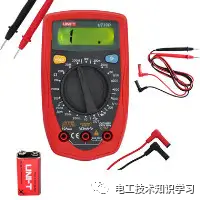 Figure 1 Below, we will briefly introduce the usage and precautions for this type of digital multimeter.
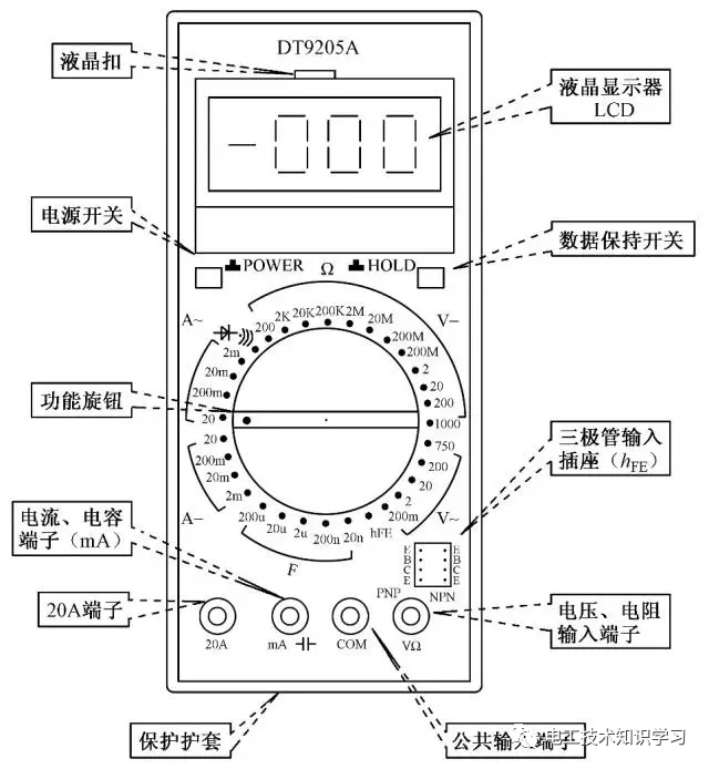
2 Appearance of Digital Multimeter
3 Usage Diagram of Digital Multimeter
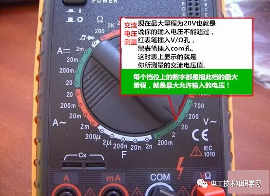
4 Measuring Voltage
1. Insert the black probe into the COM port and the red probe into the VΩ port.
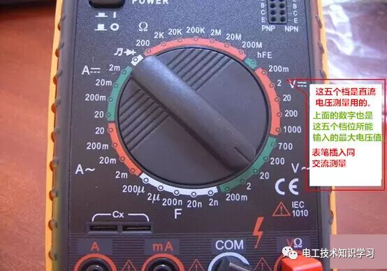
2. Rotate the function switch to V~ (AC), V- (DC), and select the appropriate range.
3. Touch the red probe to the positive terminal of the circuit being tested, and the black probe to the ground or negative terminal, effectively connecting in parallel with the circuit.
4. Read the number displayed on the LCD screen.
5 Measuring Resistance
1. Turn off the circuit power.
2. Select the resistance range (Ω).
3. Insert the black test probe into the COM input port. Insert the red test probe into the Ω input port.
4. Connect the probe tips across the two ends of the component or the part of the circuit whose resistance you want to measure.
5. Check the reading and confirm the measurement unit – ohms (Ω), kilohms (kΩ), or megohms (MΩ).
6 The Function of the Diode Beep Mode
① Judging the Condition of the Diode: Set the dial to ( ) mode, insert the red probe into the rightmost hole, and the black probe into the second hole from the right. Connect the probe tips to the two terminals of the diode as shown below, then reverse the probes and measure again.
Measurement results: If the two measurements yield: one shows “1” and the other shows a small number, then this diode is normal. If both show the same result, then this diode is damaged. The number displayed on the LCD represents the forward voltage drop of the diode: approximately 0.6V for silicon diodes; around 0.2V for germanium diodes. Based on the characteristics of the diode, you can determine that the red probe is connected to the positive terminal and the black probe is connected to the negative terminal.
② The most important characteristic of a diode is:
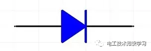
Unidirectional Conductivity
③ Short Circuit Check (Determining Circuit Continuity):
 Set the dial to the short circuit ( ) mode, with the probes positioned as above. Use the other ends of the probes to connect to the two points being tested. If these two points are indeed shorted, the multimeter will beep.
7 Measuring Current
1. Disconnect the circuit;
2. Insert the black probe into the COM port and the red probe into the mA or 20A port;
3. Rotate the function switch to A~ (AC), A- (DC), and select the appropriate range;
4. Disconnect the circuit being tested and connect the digital multimeter in series with the circuit. The current from the circuit flows into the red probe and exits from the black probe back into the circuit;
5. Reconnect the circuit;
6. Read the number displayed on the LCD screen.
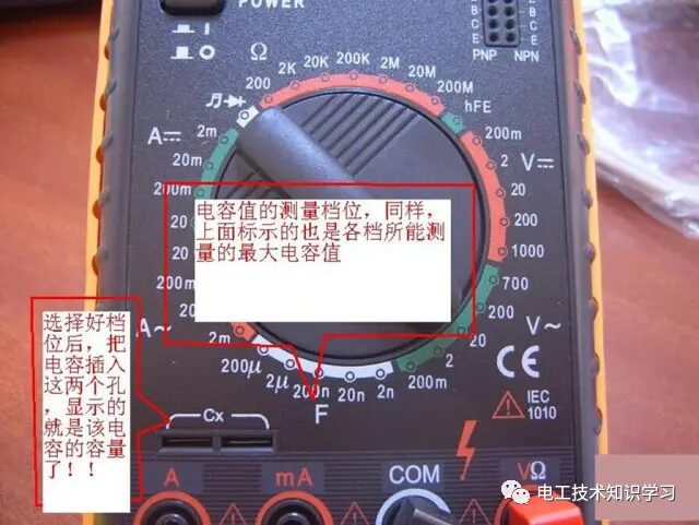
8 Measuring Capacitance
1. Short the capacitor terminals to discharge it, ensuring the safety of the digital multimeter.
2. Set the function switch to the capacitance (C) measurement range and select the appropriate range.
3. Insert the capacitor into the C-X socket of the multimeter.
4. Read the number displayed on the LCD screen.
Small Knowledge: Units of Capacitance:
1F=1000mF, 1mF=1000uF, 1uF=1000nF, 1nF=1000pF
9 Precautions for Using Digital Multimeters
1. If the voltage or current to be measured cannot be estimated in advance, first set to the highest range to measure once, and then gradually reduce the range to an appropriate level. After measurement, set the range switch to the highest voltage setting and turn off the power.
2. At full scale, the instrument will only display the digit “1” at the highest position, while other positions disappear. In this case, a higher range should be selected.
3. When measuring voltage, the digital multimeter should be connected in parallel with the circuit being tested. When measuring current, it should be connected in series with the circuit. When measuring DC, polarity does not need to be considered.
4. If the AC voltage setting is incorrectly used to measure DC voltage, or vice versa, the display will show “000” or the digits will fluctuate at low positions.
5. Do not change the range when measuring high voltages (above 220V) or large currents (above 0.5A) to prevent arcing and damage to the switch contacts.
Source: All intellectual property rights belong to the original author

★★★★★★★
Review classic articles directly by clicking
Common Mnemonics for Electricians—Collection of Household Lighting Circuits—What is a Five Protection Switch Cabinet––How to Handle Circuit Tripping—Difference Between Circuit Breakers and Residual Current Devices––Wiring Standards for Electricians––Three Standard Wiring Methods—Usage Method of Digital Multimeter—Equipment Maintenance Rules Not Told by Senior Electricians—German Low-Voltage Engineer Must Admire—Comparison of Various Switch Wiring Diagrams and Actual Diagrams—Basic Knowledge of PLC—Complete List of Electrical Symbols—Notes and Introductions for Strong and Weak Current Construction—Inspection and Maintenance Content of Low Voltage Distribution Devices—How to Create a Neutral Wire from Three-Phase to 220V —35 Common Mistakes Made by Electricians—Calculation Method for Rated Current of Motors—What is the Role of a Contactor
The spirit of selfless dedication is the basic connotation, continuously enriched and developed in practice.
Reading is a form of growth, reprinting is a form of wisdom, sharing is a virtue