The multimeter, also known as a multitester, is a multifunctional measuring instrument. Generally, a multimeter can measure DC current, DC voltage, AC voltage, resistance, and audio levels. Some can also measure AC current, capacitance, inductance, and parameters of semiconductors. It is a simple and practical measuring instrument. Nowadays, the most mainstream multimeters are digital multimeters, while analog multimeters are rarely used. Digital multimeters are relatively simple measuring devices. As a versatile electronic measuring instrument, it generally includes functions such as ammeter, voltmeter, and ohmmeter. It is sometimes referred to as a multimeter or three-use meter. The multimeter has a wide range of applications, and below we will discuss the basic usage methods of the multimeter.
Basic Usage of the Multimeter: Precautions for Using the Multimeter
(1) Before using the multimeter, perform a “mechanical zeroing”. This means setting the multimeter’s pointer to the zero voltage or zero current position when there is no measured quantity.
(2) During the use of the multimeter, do not touch the metal parts of the probes with your hands. This ensures measurement accuracy and personal safety.
(3) When measuring a certain electrical quantity, do not change the range while measuring, especially when measuring high voltage or large current. Otherwise, it may damage the multimeter. If a range change is necessary, disconnect the probes first, then change the range before measuring.
(4) The multimeter must be placed horizontally during use to avoid measurement errors. Additionally, avoid the influence of external magnetic fields on the multimeter.
(5) After using the multimeter, set the range switch to the maximum AC voltage setting. If not used for a long time, remove the internal battery to prevent corrosion of other components.
When using an analog multimeter, connect the two probes with the red probe to the positive (+) side and the black probe to the negative (-) side, then check if the pointer is at the “0” position. The pointer should align with the left end line of the scale. If not, zero adjustment is needed. Before measuring current and voltage, estimate the range of the current and voltage to be measured, set it to a larger range first, and then adjust to the appropriate range to avoid burning out the multimeter due to excessive current.
When measuring, consider the internal resistance of the multimeter. For example, to measure voltage, connect the probes to the circuit being measured. At this time, there is also current flowing through the internal resistance of the multimeter, which affects the measurement value. When measuring the voltage at the same point, if different ranges are used, the internal resistance of the multimeter differs, and the degree of influence also varies.
When measuring transistor circuits, it is better to select a DC range with an internal resistance of 20kΩ/V, which is usually indicated on the multimeter scale. Additionally, transistor circuits often need to measure low voltage, such as 0.1V, so the selected multimeter should have a measurement range of 1V.
Basic Usage of the Multimeter: Using the Ohm Range
1. Select the appropriate range. When measuring resistance with the ohmmeter, select an appropriate range, so the pointer indicates near the middle value. It is best not to use the left third of the scale, as this part has poor scale density.
2. Adjust to zero before use.
3. Do not measure with power on.
4. The measured resistance must not have parallel branches.
5. When measuring the equivalent resistance of polarized components such as transistors and electrolytic capacitors, pay attention to the polarity of the two probes.
6. When measuring the equivalent resistance of nonlinear components with different ranges, the measured resistance values will differ. This is due to the different mid-range resistances and full-scale currents of each range. In mechanical meters, the smaller the range, the smaller the measured resistance value.
Basic Usage of the Multimeter: Using the Diode Range
First, we learn the simplest diode range. Rotate the multimeter’s knob to the position marked with the diode symbol, then short the two probes. You will hear a beep from the buzzer, indicating that this range can be used normally, and also confirming that the resistance between the two probes is zero. This is commonly used to measure whether there is a break in the circuit and whether the components are electrically connected. Since this is the diode range, we can use it to measure the forward voltage drop of the diode. During measurement, place the red probe on the anode of the diode and the black probe on the cathode. The display will directly show the voltage drop value. Additionally, this range can also determine whether the diode is a silicon diode or a germanium diode, as well as whether the diode is damaged.
Basic Usage of the Multimeter: Using the Resistance Range
From the diode range, rotating clockwise, you can see the resistance range, denoted by the Ω symbol. When measuring, we should first determine the size of the resistance, then select the knob to choose the range. If you are unsure of the resistance size, you can try measuring with a middle range first, and then switch to the appropriate range based on the estimated value. For example, if we use a 1K resistor for testing, we should switch to the 2K range and then read the value directly from the display. As for the pointer part, since resistance has no positive or negative distinction, the red and black probes can be connected to either side of the resistor (do not touch the probes when measuring large resistances), regardless of polarity.
Basic Usage of the Multimeter: Using the Transistor Range
Rotate the knob clockwise to reach the hFE range. This range is used to measure the amplification parameters of transistors. Generally, there are two sockets: one for NPN and the other for PNP. Before measuring, we must distinguish whether it is an NPN or PNP transistor. Here we use an NPN type. Since the transistor has three pins, each pin has a different function. After correctly identifying the pins, insert them into the measurement sockets according to the pin names. The amplification factor of the transistor can be read directly from the display.
Basic Usage of the Multimeter: Using the Voltage Range
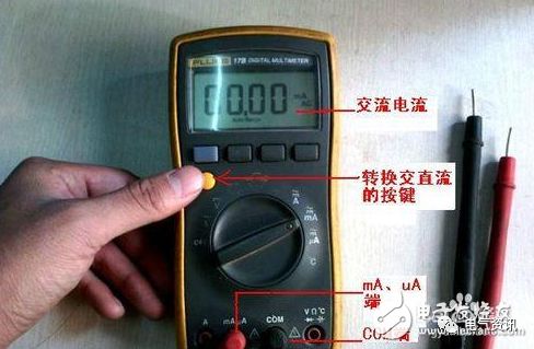
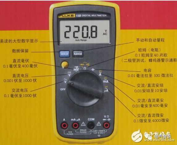
Next, rotate the measuring knob to the voltage range. In this multimeter, both the AC and DC ranges fall within this range. Therefore, before measuring, we should first determine whether we are measuring AC or DC voltage. If the selected type is not the one to be measured, the AC/DC switch can be pressed to change the range (some multimeters have separate switches for AC and DC, which do not have a switching button). Additionally, select an appropriate range. If you do not know the voltage to be measured beforehand, you must select the maximum range. Common household AC voltage is 220V, and a typical DC voltage can be exemplified by the 5V output of a computer USB port.
Basic Usage of the Multimeter: Using the Frequency Counter Range
Continuing clockwise, the next range is for measuring frequency. The dial shows 10MHz, indicating that the maximum measurable frequency value is 10KHz. When measuring, connect the probes to both ends of the frequency counter, and the measurement value can be read directly from the display. Ensure that the red probe is connected to the positive terminal of the signal source, and the black probe is connected to the negative terminal.
Basic Usage of the Multimeter: Using the Capacitance Range
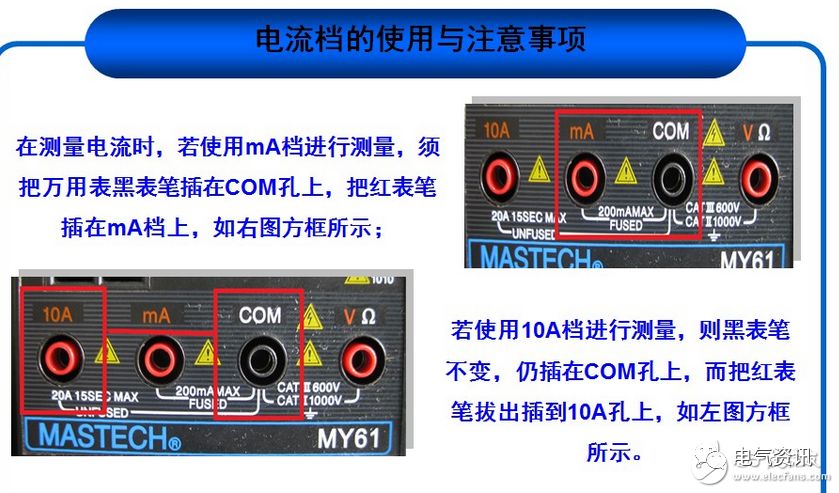
Sometimes we also use the multimeter to measure capacitance. The first step is to determine the size of the capacitance and select the multimeter range accordingly. After selection, place the probes on both ends of the capacitor, without needing to distinguish between positive and negative terminals. If it is a polarized capacitor, it can also be measured directly without distinguishing the positive and negative terminals. The capacitance size can be read directly from the display. Additionally, it is important to note that when measuring capacitance, the red probe must be inserted into the mA socket; only in this socket can measurement results be obtained.
Basic Usage of the Multimeter: Tips for Measuring DC
1. Perform mechanical zeroing.
2. Select the appropriate range.
3. When using the multimeter to measure current, it should be connected in series with the circuit being measured, as only series connection allows the current flowing through the ammeter to be the same as the current in the measured branch. During measurement, disconnect the measured branch and connect the red and black probes in series between the two disconnected points. It is particularly important to note that the ammeter should not be connected in parallel with the circuit being measured, as this can be very dangerous and easily burn out the multimeter.
4. Pay attention to the polarity of the measured electrical quantity.
5. Correctly use the scale and read the values.
6. When selecting the 2.5A range for DC current, the red probe should be plugged into the 2.5A measurement socket, and the range switch can be set to any range in the DC current section.
7. If the measured DC current exceeds 2.5A, the 2.5A range can be expanded to the 5A range. This is simple; the user can connect a 0.24-ohm resistor between the “2.5A” socket and the black probe socket, thus changing the range to 5A. The 0.24-ohm resistor should be selected to be above 2W; otherwise, it may burn out.
Currently, multimeters are divided into analog and digital types, each with its conveniences. It is hard to say which is better; it is best to have one of each. For amateur electronic projects, an MF30 type analog multimeter is sufficient, as it is a classic model. There is also the veteran MF500 type multimeter and the inexpensive MF50 multimeter, which can generally be found in telecommunications stores.
The three basic functions of the multimeter are measuring resistance, voltage, and current, which is why it is called a three-use meter. Modern multimeters have added many new functions, especially digital multimeters, such as measuring capacitance, transistor amplification factors, diode voltage drops, etc. There is even a talking digital multimeter that can announce the measurement results verbally (which is not too difficult; Bitbaby once wanted to make one using a microcontroller and voice circuit :-))
Digital multimeters also have many classic models, such as DT830C, DT890D, etc. The suffix indicates differences in function; for example, DT830C can be purchased for over thirty yuan, which is quite cheap. Bitbaby once assembled an MF50 multimeter at school; the circuit principle is not complicated, but the numerous components were not fixed on a printed circuit board but directly soldered onto a terminal board, making it somewhat troublesome for beginners.
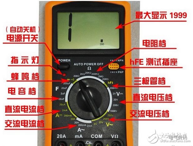
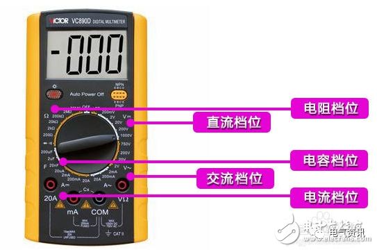
The biggest feature of the multimeter is the range switch, which is used to switch between various functions. Generally, A- represents measuring DC current, with milliamp and amp ranges divided into several sections. V- represents measuring DC voltage, while higher-end multimeters have millivolt ranges, and voltage ranges are also divided into several sections. V~ is used to measure AC voltage. A~ measures AC current. The Ω ohm range measures resistance. For analog multimeters, each time the resistance range is changed, zero adjustment must also be performed. Zero adjustment means connecting the red and black probes together and turning the zero adjustment knob to make the pointer point to zero.
The following uses the MF30 type multimeter as an example to explain the reading. The first scale line indicates the resistance value, with the leftmost end being infinite and the rightmost being zero, with uneven scales in between. The resistance range has R×1, R×10, R×100, R×1K, R×10K, each indicating that the scale reading must be multiplied by a corresponding factor to obtain the actual resistance value (in ohms).
For example, when measuring a resistor with the R×100 range, if the pointer indicates “10”, then its resistance value is 10×100=1000, or 1K. The second scale line is shared by the 500V and 500mA ranges. It is important to note that the indication principles for voltage and current ranges differ from that of the resistance range. For example, the 5V range indicates that it can only measure voltages below 5V, and the 500mA range can only measure currents below 500mA; exceeding the range can damage the multimeter.
Precautions: The multimeter should be placed horizontally during use. The red probe should be plugged into the + socket, and the black probe should be plugged into the – socket. Use the current range for testing current, not the voltage or resistance ranges, and vice versa; otherwise, it may burn the multimeter’s fuse or even damage the meter head. If the pointer quickly deflects to the end, immediately disconnect the circuit and check.
Lastly, there is a rule: after use, the multimeter should be set to the highest AC voltage range to prevent someone from accidentally measuring 220V AC voltage and damaging it. Remember this fine tradition left by the predecessors!
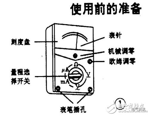
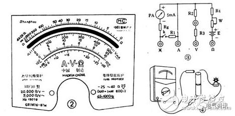
The multimeter is used to measure AC and DC voltage, resistance, DC current, etc. It is an essential tool for electricians and radio enthusiasts. At first glance, the multimeter seems complex; in reality, it consists of an ammeter (commonly known as a meter head), a scale dial, a range selection switch, and probes, as shown in Figure 1. When using, if the range selection switch points to the DC current range, the ammeter M is connected with some shunt resistors to expand the range (Rg is the meter head resistance), making it a current meter with several different ranges. The measurement result is read from the DC current scale on the dial. Usually, the second line on the dial indicates the current scale, as shown in Figure 2. Similarly, if the range selection switch points to the DC voltage range, the meter head is connected in series with other resistors (like R2, R3, using the principle of voltage division with series resistors), making it a multi-range voltage meter, as seen in Figure 3. The reading should be taken from the DC voltage scale on the dial. Most multimeters share a scale for voltage and current. If a rectifier is connected in a circuit measuring DC voltage, it can measure AC voltage. The principle for measuring resistance is similar to that of measuring DC voltage, except that an additional battery is required for testing. When the selection switch points to the resistance range, the first line of the scale should be used to read the resistance value. There are many types of multimeters, but their basic usage methods are the same.
Basic Usage of the Multimeter: Taking the MF30 Type Multimeter as an Example, Introducing Its Usage Methods.
First, before using the multimeter, familiarize yourself with the function of the range selection switch. Clearly determine what you want to measure and how to measure it, and then set the range selection switch to the required testing range. Be careful not to make mistakes with the range. For example, when measuring voltage, if the selection switch is mistakenly set to current or resistance, it can easily burn out the meter head.
Second, observe whether the pointer is at the zero position before use. If it is not at the zero position, use a screwdriver to adjust the mechanical zeroing screw on the meter head to bring the pointer back to zero (generally, this does not need to be done every time). The red probe should be plugged into the positive socket, and the black probe should be plugged into the negative socket.
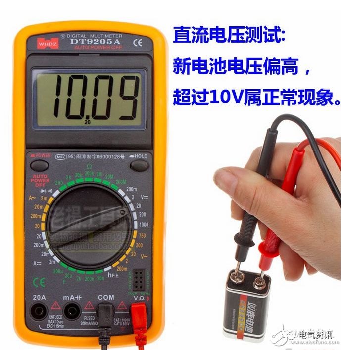
For voltage measurement, point the range selection switch to the V range within the five ranges. If measuring AC voltage, it should point to V. Similarly, if you want to change to measure resistance, the switch should point to the resistance range. For current measurement, it should point to mA or μA. Example 1 is measuring the voltage of a dry battery, see Figure 4.
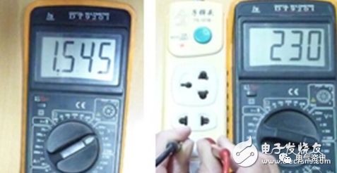
When measuring voltage, connect the multimeter probes in parallel with the circuit being measured. Based on the approximate value of the measured circuit, select an appropriate range position. The maximum value of each dry battery is 1.5V, so it can be placed in the 5V range. At this time, the full-scale reading of the pointer on the panel, which is 500, should be read as 5, which is 100 times smaller. If the pointer indicates the 300 scale, it should be read as 3V. Note that the value indicated by the range switch should be multiplied by the corresponding value of the full-scale reading on the meter head to obtain the actual value. This method applies to all ranges except the resistance range. In practical measurements, if you cannot determine the approximate value of the voltage to be measured, you can first set the switch to the maximum range and then gradually decrease the range to an appropriate position. When measuring DC voltage, pay attention to the positive and negative polarities. If the probes are reversed, the pointer will deflect in the opposite direction. If the polarity of the circuit is unknown, set the multimeter to the maximum range, quickly test it on the measured circuit, and observe how the pointer deflects to determine the positive and negative polarities.
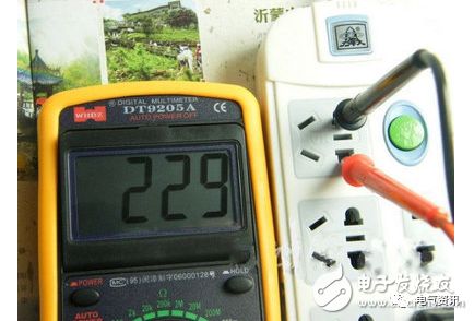
Example 2, measuring 220V AC. Set the range switch to the AC 500V range. The full scale is 500V, and the reading is taken directly from the scale. Insert the two probes into the power socket, and the position indicated by the pointer is the measured voltage value. When measuring AC voltage, the probes have no positive or negative distinction.
Basic Usage of the Multimeter: One, Choosing Between Analog and Digital Meters:
1. Analog meters have poorer reading accuracy, but the process of the pointer swinging is relatively intuitive. The swing speed and amplitude can sometimes objectively reflect the size of the measured value (for example, measuring the slight jitter of the data bus (SDL) when transmitting data on a TV); digital meters provide straightforward readings, but the process of changing numbers appears chaotic and is not easy to observe.
2. Analog meters generally have two batteries, one low voltage 1.5V and one high voltage 9V or 15V, with the black probe being positive relative to the red probe. Digital meters commonly use a single 6V or 9V battery. In the resistance range, the output current of the probes from an analog meter is significantly larger than that of a digital meter, which can produce a loud “click” sound in the R×1Ω range and even light up an LED in the R×10kΩ range.
3. In the voltage range, the internal resistance of the analog meter is relatively small compared to the digital meter, which leads to poorer measurement accuracy. In some high-voltage microcurrent situations, it may even be unable to measure accurately because its internal resistance would affect the measured circuit (for instance, when measuring the accelerating voltage of a TV tube, the measured value would be much lower than the actual value). The voltage range of digital meters has a very high internal resistance, at least in the megaohm range, which has little effect on the measured circuit. However, the extremely high output impedance makes it susceptible to induced voltages, and in environments with strong electromagnetic interference, the data obtained may be false.
4. In summary, analog meters are suitable for measuring relatively large currents and high voltages in analog circuits, such as televisions and audio amplifiers. Digital meters are suitable for measuring low-voltage and low-current digital circuits, such as pagers and mobile phones. This is not absolute, and selection can depend on the situation.
Basic Usage of the Multimeter: Two, Measurement Techniques (if not specified, it refers to the analog meter):
1. Measuring speakers, headphones, and dynamic microphones: Use the R×1Ω range. Connect one probe to one end and touch the other probe to the other end. Normally, a clear “click” sound will be heard. If there is no sound, the coil is broken. If the sound is small and sharp, there is a problem with the diaphragm, and it cannot be used.
2. Measuring capacitance: Use the resistance range and select an appropriate range based on the capacitance size. When measuring electrolytic capacitors, ensure that the black probe connects to the positive terminal of the capacitor.
① Estimate the size of microwave-level capacitors: You can rely on experience or refer to a standard capacitor of the same capacity, judging by the maximum amplitude of the pointer swing. The reference capacitor does not need to have the same voltage rating; as long as the capacity is the same, for example, to estimate a 100μF/250V capacitor, you can use a 100μF/25V capacitor for reference. As long as their pointer swings to the same maximum amplitude, you can conclude that their capacitance is the same.
② Estimate the size of picofarad-level capacitors: Use the R×10kΩ range, but it can only measure capacitors above 1000pF. For capacitors around 1000pF or slightly larger, if the pointer swings slightly, it can be considered sufficient capacitance.
③ Check for leakage in capacitors: For capacitors above one thousand microfarads, first use the R×10Ω range to quickly charge them and roughly estimate the capacitance size, then switch to the R×1kΩ range to continue measuring. The pointer should not return but should stop at or very close to ∞; otherwise, it indicates leakage. For timing or oscillation capacitors (like those in color television switch power supplies), the leakage characteristics are very strict; even slight leakage renders them unusable. In this case, after charging in the R×1kΩ range, switch to R×10kΩ to continue measuring, and the pointer should also stop at ∞ and not return.
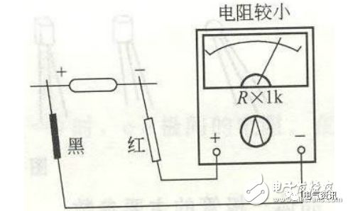
3. Measuring the condition of diodes, transistors, and voltage regulators: Since the bias resistance of transistors in actual circuits or the surrounding resistance of diodes and voltage regulators is generally large (usually several hundred to several thousand ohms), we can use the R×10Ω or R×1Ω range of the multimeter to measure the PN junction’s condition. When measuring in-circuit, the PN junction should show a significant forward and reverse characteristic when measured with the R×10Ω range (if the forward and reverse resistances are not significantly different, you can switch to the R×1Ω range). Typically, the forward resistance measured in the R×10Ω range should indicate around 200Ω, while in the R×1Ω range, it should indicate around 30Ω (these values may slightly vary depending on the meter type). If the forward resistance reading is too high or the reverse resistance is too low, it indicates that the PN junction has issues, and thus the component is faulty. This method is particularly effective for repairs, allowing for quick identification of faulty components, even detecting those that haven’t completely failed but have deteriorated in performance. For example, if you measure a certain PN junction’s forward resistance with a low resistance range and find it excessively high, if you desolder it and measure it with the commonly used R×1kΩ range, it may still appear normal; however, the component’s characteristics have already degraded, rendering it unable to function properly or stably.
4. Measuring resistance: It is important to select the appropriate range. Measurement accuracy is highest when the pointer indicates between 1/3 to 2/3 of the full scale. Note that when measuring megaohm-level resistors with the R×10kΩ range, do not touch the probes with your fingers, as this will add the resistance of your body and skew the measurement results.
5. Measuring Zener diodes: The Zener diodes we commonly use generally have a Zener voltage greater than 1.5V, while the resistance ranges below R×1k on analog meters are powered by a 1.5V battery. Thus, measuring Zener diodes in the R×1k range behaves like measuring a diode, exhibiting complete unidirectional conductivity. However, the R×10k range on analog meters is powered by a 9V or 15V battery. When measuring Zener diodes with a Zener voltage below 9V or 15V in the R×10k range, the reverse resistance will not be ∞ but will have a certain resistance value. However, this value will still be significantly higher than the forward resistance of the Zener diode. Therefore, we can preliminarily estimate the condition of the Zener diode. But a good Zener diode must also have an accurate Zener voltage. Under amateur conditions, how can we estimate this Zener voltage? It’s not difficult; just find another analog meter. The method is: first set one meter to the R×10k range, connecting the black and red probes to the cathode and anode of the Zener diode, respectively, simulating the actual working state of the Zener diode. Then take another meter, set it to the voltage range, V×10V or V×50V (based on the Zener voltage), and connect the red and black probes to the corresponding probes of the first meter. The voltage measured will be approximately the Zener voltage of the diode. It should be noted that the first meter’s bias current is slightly lower than the normal operating bias current, so the measured Zener voltage will be slightly higher, but the difference is generally small. This method can only estimate the Zener voltage of diodes with Zener voltages below the high voltage of the analog meter’s battery. If the Zener voltage is too high, it can only be measured using an external power supply (thus, when choosing an analog meter, those with a higher battery voltage of 15V are more suitable than those with 9V).
6. Measuring transistors: Typically, we use the R×1kΩ range, regardless of whether it is an NPN or PNP transistor, or whether it is a small, medium, or large power transistor. The BE junction and CB junction should exhibit the same unidirectional conductivity as a diode, with infinite reverse resistance. The forward resistance should be around 10K. To further estimate the characteristics of the component, it is necessary to change the resistance range for multiple measurements. The method is: set the meter to the R×10Ω range; the forward conduction resistance of the PN junction should be around 200Ω; set it to the R×1Ω range, and the forward conduction resistance should be around 30Ω (the above values are for a type 47 meter; other models may vary slightly, so it is good to test several good components to get a baseline). If the readings are excessively high, it indicates poor characteristics of the component. The meter can also be set to R×10kΩ and measured; even for low-voltage transistors (most transistors have a breakdown voltage above 30V), the reverse resistance of the CB junction should be ∞, but the BE junction may show slight deflection, with the pointer not exceeding 1/3 of the full scale (depending on the transistor’s breakdown voltage). Similarly, when measuring the CE junction resistance using R×10kΩ, the pointer may show slight deflection, but this does not indicate the component is faulty. However, if the resistance is measured with R×1kΩ or lower and shows a finite value, the transistor is faulty. It should be noted that these measurements apply to silicon transistors and are not suitable for germanium transistors, which are now rare. Also, the term “reverse” refers to the PN junction; for NPN and PNP transistors, the directions are actually different.
Basic Usage of the Multimeter: Using Cases–Accurately Identifying the Pins of a Transistor (B, C, E) Using a Multimeter:
Most commonly used transistors are encapsulated in plastic. How can we accurately identify which of the three pins is B, C, or E?

Basic Usage of the Multimeter: Here are Three Recommended Methods:
The first method: For analog meters with hFE measurement sockets, first measure the B pin, then insert the transistor randomly into the socket (of course, the B pin can be inserted correctly), measure the hFE value, and then turn the component upside down and measure again. The higher hFE value indicates that the pin positions are correct.
The second method: For meters without hFE measurement sockets, or when the component is too large to fit into the socket, you can use this method: For NPN transistors, first measure the B pin (it is easy to measure whether the transistor is NPN or PNP and find the B pin, right?). Set the meter to the R×1kΩ range, connect the red probe to the assumed E pin (be careful not to touch the probe tip or pin with your hand), and connect the black probe to the assumed C pin. While holding the probe tips and this pin, lift the transistor and lick the B pin with your tongue. If the probes are connected correctly, the pointer will deflect significantly; if not, it will deflect less, and the difference is very noticeable. Thus, you can determine the C and E pins of the transistor. For PNP transistors, connect the black probe to the assumed E pin and the red probe to the assumed C pin, then lick the B pin with your tongue. If the probes are connected correctly, the pointer will deflect more. Of course, you should switch the probes and measure twice, comparing the readings to make the final determination. This method is suitable for all shapes of transistors and is convenient and practical. Based on the pointer’s deflection, you can also estimate the transistor’s amplification capability, but this is based on experience.
The third method: First determine the type of the transistor (NPN or PNP) and the B pin, then set the meter to the R×10kΩ range. For NPN transistors, connect the black probe to the E pin and the red probe to the C pin; the pointer may show some deflection. For PNP transistors, connect the black probe to the C pin and the red probe to the E pin; the pointer may show some deflection. Reversing the connections will not show any deflection. This method can also be used to determine the C and E pins. However, this method is not applicable for high-voltage transistors. For commonly used imported large power encapsulated transistors, the C pin is generally in the middle (I have not seen B in the middle). For medium and small power transistors, the B pin may sometimes be in the middle. For example, in commonly used transistors like the 9014 and its series, as well as the 2SC1815, 2N5401, 2N5551, etc., the B pin may be in the middle. Therefore, when repairing or replacing transistors, especially these small power transistors, do not just install them as they are; always measure first.
Basic Usage of the Multimeter: Multimeter Usage Mnemonics
Correct use of the multimeter not only allows for quick and accurate identification of faulty components but also prevents damage to electrical devices and the multimeter itself.
1. Check the range before measuring; don’t measure without checking.
Every time you pick up the probes to prepare for measurement, always double-check whether the measurement category and the range selection switch are set correctly. For safety, this habit must be developed.
2. Do not change the range during measurement; after measuring, set it to the off position.
During measurement, do not randomly turn the selection knob, especially when measuring high voltage (like 220V) or large currents (like 0.5A), to avoid generating arcs and burning out the switch contacts. After completing the measurement, set the range selection switch to the “•” position.
3. The dial should be level, and the reading should be aligned.
When using the multimeter, it should be held horizontally, and the line of sight should be directly in line with the pointer when reading.
4. The range should be appropriate; the pointer should deflect more than half.
Select the range; if you cannot estimate the measured value beforehand, try to choose a larger range, then gradually switch to a smaller range based on the deflection angle until the pointer deflects to about 2/3 of the full scale.
5. Do not measure resistance with power on; discharge capacitors before measuring.
It is strictly forbidden to measure resistance in a live circuit. When checking large capacitors on electrical devices, discharge them first before measuring.
6. Zero adjustment is required before measuring resistance; zero adjustment is needed when changing ranges.
When measuring resistance, first set the selection switch to the resistance range, short the two probes, and adjust the “Ω” zero potentiometer to make the pointer point to zero before measuring. Each time the resistance range is changed, the zero point must be readjusted.
7. Remember the black is negative; the black probe connects to the positive inside.
The red probe is positive, and the black probe is negative, but in the resistance range, the black probe connects to the internal battery’s positive terminal.
8. For current measurement, connect in series; for voltage measurement, connect in parallel.
When measuring current, the multimeter should be connected in series with the circuit being measured; when measuring voltage, the multimeter should be connected in parallel across the two ends of the circuit being measured.
9. Ensure the polarities are not reversed; develop the habit of using one hand.
When measuring current and voltage, pay special attention to ensure the red and black probes are not reversed, and always develop the habit of using one hand to ensure safety.
Source: Electronic Enthusiasts
If there is any infringement, please contact for removal.