A multimeter is an instrument used to measure parameters such as voltage, current, and resistance. It comes in two types: analog and digital, as shown in Figure 1.
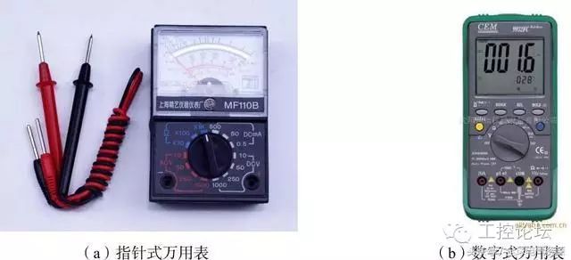
Figure 1 Multimeter


(1) Place it horizontally. Position the multimeter horizontally.
(2) Check the needle. Check if the multimeter needle is at the “zero” position on the left end of the dial. If it is not at “zero”, gently turn the mechanical zero adjustment knob on the meter head with a small screwdriver to align the needle at “zero”, as shown in Figure 2.
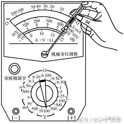
Figure 2 Mechanical Zero Adjustment of Multimeter
(3) Insert the probes correctly. Insert the red and black probes into the respective sockets.
(4) Check the battery. Set the range selection switch to resistance R × 1, short the red and black probes, and if after performing “ohm zero adjustment” the multimeter needle still cannot reach the zero position on the scale, it indicates that the voltage is insufficient and the battery needs to be replaced.
(5) Select the measurement item and range. Rotate the range selection switch to the corresponding item and range. Do not switch the range selection switch while measuring under power to avoid potential arcing that could damage the switch contacts.


(1) Measuring Current
① Select the range. The current range on the multimeter is marked with “mA” and has different ranges such as 1 mA, 10 mA, 100 mA, 500 mA, etc. Choose an appropriate range based on the current being measured. If the current size is unknown, first measure with the maximum current range and gradually switch to the appropriate range.
② Measurement method. Connect the multimeter in series with the circuit to be tested. Disconnect the corresponding part of the circuit and connect the multimeter probes at the two ends of the break. For DC current, connect the red probe to the break connected to the positive terminal of the circuit and the black probe to the break connected to the negative terminal of the circuit, as shown in Figure 3.7.
③ Read the value correctly. Carefully observe the scale dial, find the corresponding scale line, and read the measured voltage value. Note that when reading, your line of sight should be directly aligned with the needle.
(2) Measuring Voltage
① Select the range. The DC voltage range on the multimeter is marked with “V” and has different ranges such as 2.5 V, 10 V, 50 V, 250 V, and 500 V. Choose an appropriate range based on the voltage being measured. If the voltage size is unknown, first measure with the highest voltage range and gradually switch to the appropriate range.
② Measurement method. Connect the multimeter in parallel across the two ends of the circuit to be tested. For measuring DC voltage, connect the red probe to the positive terminal of the circuit and the black probe to the negative terminal of the circuit, as shown in Figure 4.
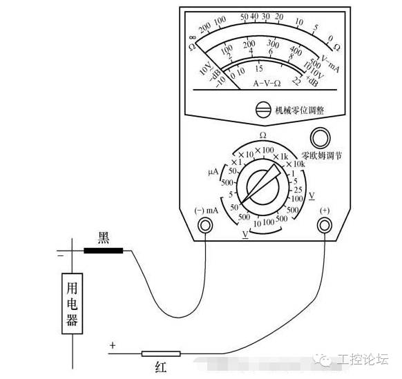
Figure 3 Measuring DC Current with Multimeter
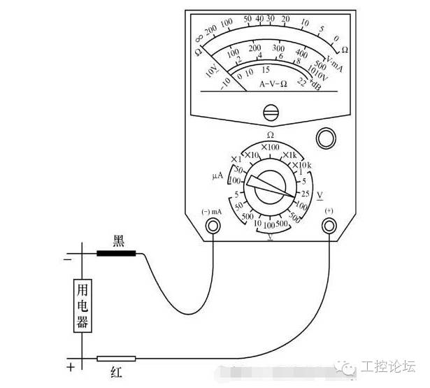
Figure 4 Measuring DC Voltage with Multimeter
③ Read the value correctly. Carefully observe the scale dial, find the corresponding scale line, and read the measured voltage value. Note that when reading, your line of sight should be directly aligned with the needle.
(3) Measuring Resistance
① Select the range. The resistance range on the multimeter is marked with “Ω” and has different ranges such as R × 1, R × 10, R × 100, R × 1k, R × 10k, etc. Choose the appropriate range based on the size of the resistance being measured, and try to keep the needle close to the center position, as this minimizes error, as shown in Figure 5 (a).
② Ohm zero adjustment. Short the red and black probes; if the multimeter needle cannot fully deflect (the needle cannot move to the zero position on the right end of the scale), perform “ohm zero adjustment”, as shown in Figure 5 (b).
③ Measurement method. Disconnect the resistance from other components or power supply, hold the probes with one hand, and connect them across the two ends of the resistance, as shown in Figure 5 (c).
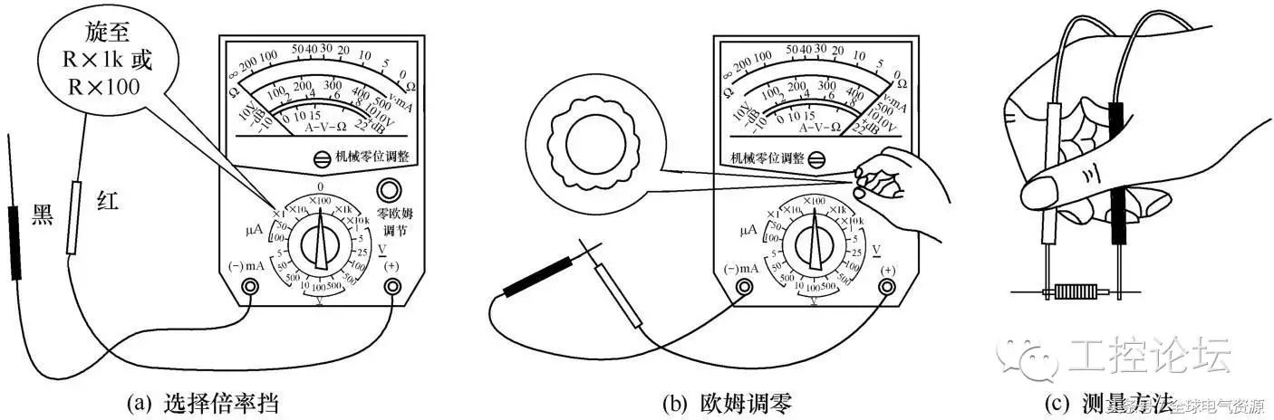
Figure 5 Measuring Resistance with Multimeter
④ Read the value correctly. When reading, first determine the minimum scale value based on the position of the needle, then multiply by the range factor to get the actual resistance value. For example, if the needle indicates a value of 18.1Ω and the selected range is R × 100, then the measured resistance value is 1,810Ω.
⑤ After switching ranges, always adjust the “ohm zero adjustment” knob again before measuring.


(1) After each use, remove the probes.
(2) Set the range selection switch to “OFF” or to the highest AC voltage range to prevent accidental damage to the multimeter during the next measurement.
(3) If the multimeter will not be used for a long time, remove the battery to prevent leakage of the battery electrolyte, which could corrode the internal circuit, as shown in Figure 6.
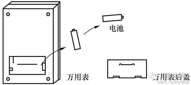
Figure 6 Maintenance of Multimeter
(4) Keep the multimeter dry and clean, and avoid vibration and mechanical impact.


1. Measuring Potentiometers
A potentiometer, also known as a variable resistor, is a resistor whose resistance can be freely adjusted within a certain range. The multimeter can measure the nominal resistance and resistance changes of the potentiometer, as shown in Figure 7.
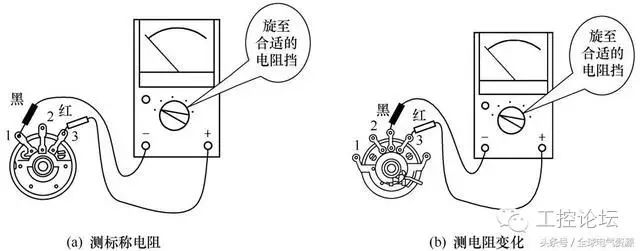
Figure 7 Specific Method for Measuring Potentiometer with Multimeter
(1) Select the range. Rotate the range selection switch to the appropriate resistance range.
(2) Measure the nominal resistance. Measure the resistance between terminals 1 and 3 of the potentiometer; this resistance is the nominal resistance of the potentiometer, as shown in Figure 7 (a). If the resistance is infinite, it indicates that the potentiometer is internally open.
(3) Measure the resistance change. While slowly turning the shaft of the potentiometer, measure whether the resistance between terminals 1 and 2 or between terminals 2 and 3 changes continuously and uniformly, as shown in Figure 7 (b). If there is a discontinuous change or jumping phenomenon in the resistance, it may indicate that there is a problem with uneven resistance change or poor contact in the potentiometer.
(4) Determine the type of potentiometer. When the potentiometer rotates uniformly, if the multimeter needle also deflects uniformly, it indicates that it is a linear potentiometer; if the multimeter needle deflects quickly at first (or slowly) and then slows down (or speeds up) towards the end, it indicates that it is an anti-logarithmic or logarithmic potentiometer.
2. Measuring Capacitors with the Multimeter
A capacitor is a common component consisting of two metal plates separated by an insulating material (dielectric). The multimeter can perform qualitative and semi-quantitative quality tests on capacitors. The basic method for measuring capacitors with a multimeter is shown in Figure 8.
① Select the range. Rotate the range selection switch to the appropriate resistance range (R × 1k or R × 10k).
② Measure ordinary capacitors. When measuring larger capacitors (above 5,000pF), the multimeter needle will quickly swing to the right and then gradually return to the left end. The resistance value indicated when the needle stops is the insulation resistance of the capacitor. The larger the insulation resistance, the better; it should generally be close to infinity, as shown in Figure 8 (a). When measuring smaller capacitors (below 5,000pF), the multimeter needle will hardly move.
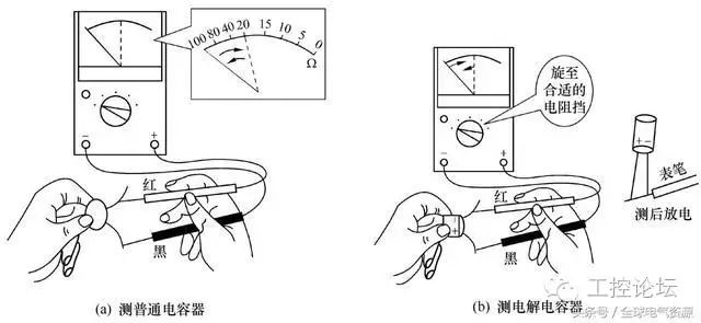
Figure 8 Basic Method for Measuring Capacitors with Multimeter
③ Measure electrolytic capacitors. Electrolytic capacitors are polarized capacitors. When testing, connect the red probe to the negative terminal of the electrolytic capacitor and the black probe to the positive terminal; the larger the capacitance, the greater the needle swing, as shown in Figure 8 (b). After each measurement, short the two ends of the capacitor with the probes to discharge it.
Source: “Repair Electrician and Training – Beginner Edition”, Author: Jin Guodi
If you have better articles or videos, feel free to submit them. Submission email: [email protected]. There are surprises for submissions!
—————End—————-
Long press the QR code to follow the forum.