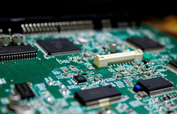
In the field of electronic engineering, debugging (Debug) circuit boards is an indispensable part of the product development process, directly related to whether the product’s functions and performance meet the standards. In the face of complex digital circuit systems, an efficient and organized Debug process is particularly important. So how can we effectively perform its Debug?
1. Power Check
Voltage Verification: Use a multimeter or oscilloscope to confirm that the voltage values at all power points meet design requirements, including main power, auxiliary power, and any specific voltage requirements.
Power-up Sequence and Stability: For power systems that require a specific power-up sequence, confirm that the power startup order meets design requirements and observe the stability of the power supply.
2. Clock Signal Analysis
Frequency and Waveform: Use an oscilloscope to check that all clock signals have accurate frequencies, clear waveforms, and clean edges (no non-monotonic phenomena).
Phase Relationship: For systems with multiple clock domains, confirm that the phase relationships between clock signals meet design requirements.
3. Reset Signal Confirmation
Effectiveness and Timing: Verify that the Reset signal can be correctly activated when the system starts and released after the system is stable. At the same time, check that the timing of the Reset signal meets the requirements of the chip or system.
4. Basic Function Testing
Initial Signals: After powering on the system and ensuring that the clock and Reset signals are normal, observe whether there is an expected initial signal output, such as startup signals, status indicators, etc.
Single Board Testing: If possible, first conduct functional tests on the single board to ensure that each independent module or component operates normally.
5. System Logic and Protocol Verification
Logical Functions: According to the system architecture design, gradually verify whether the logical functions of each functional module are correctly implemented.
Communication Protocol: For circuit boards involving communication, test the correctness and stability of the communication interfaces according to communication protocol standards (such as I2C, SPI, UART, etc.).
6. Fault Localization and Repair
Signal Tracing: Use tools such as logic analyzers and oscilloscopes to trace abnormal signals and locate the problem.
Hardware Replacement: When the problem cannot be resolved at the software or firmware level, consider the possibility of hardware failure and gradually replace suspected faulty components.
Software Debugging: For programmable devices (such as FPGA, MCU), perform software-level debugging in conjunction with simulation tools and debugging environments.
7. Stability and Reliability Testing
Long-term Operation: Let the system run continuously for a period and observe whether there are any instability phenomena.
Environmental Adaptability: Test the stability and reliability of the system under different environmental temperatures, humidity, and other conditions.
This article is an original work by Fan Yi Education, please indicate the source when reprinting!