This example is a gas leak and fire alarm system based on the STM32F103C6. Below is the complete project configuration and code.Note: Sensor module link Proteus Sensor Library Collection
1. STM32CubeMX Configuration
Clock Configuration
-
Using HSI RC clock (8MHz)
-
System clock: 8MHz
-
AHB prescaler: No prescaling
-
APB1 prescaler: No prescaling
-
APB2 prescaler: No prescaling
GPIO Configuration
| Pin | Mode | Function |
|---|---|---|
| PB10 | Output Push Pull | LCD_RS |
| PB11 | Output Push Pull | LCD_E |
| PB12 | Output Push Pull | LCD_D4 |
| PB13 | Output Push Pull | LCD_D5 |
| PB14 | Output Push Pull | LCD_D6 |
| PB15 | Output Push Pull | LCD_D7 |
| PA3 | Input | Gas sensor input |
| PA4 | Input | Fire sensor input |
| PA2 | Output Push Pull | Gas alarm buzzer |
| PA9 | Output Push Pull | Fire alarm buzzer |
| PA1 | Output Push Pull | Fan drive |
| PA6 | Output Push Pull | Gas leak indicator light |
2. Keil Code Implementation
#include “main.h”
#include “stdio.h”
#include “lcd_txt.h”
TIM_HandleTypeDef htim2;
void SystemClock_Config(void);
static void MX_GPIO_Init(void);
static void MX_TIM2_Init(void);
int main(void)
{
HAL_Init();
/* Configure the system clock */
SystemClock_Config();
/* USER CODE BEGIN SysInit */
/* USER CODE END SysInit */
/* Initialize all configured peripherals */
MX_GPIO_Init();
MX_TIM2_Init();
/* USER CODE BEGIN 2 */
lcd_init();
/* USER CODE END 2 */
/* Infinite loop */
/* USER CODE BEGIN WHILE */
while (1)
{
if(HAL_GPIO_ReadPin(GPIOA, GPIO_PIN_3)) // if the pin is HIGH
{
HAL_GPIO_WritePin(GPIOA, GPIO_PIN_2, 0);
HAL_GPIO_WritePin(GPIOA, GPIO_PIN_1, 0);
lcd_puts(0, 0, (int8_t*)”GAS DETECTED: Y”);
lcd_puts(1, 0, (int8_t*)”FAN ACTIVATED! “);
}
else if(!HAL_GPIO_ReadPin(GPIOA, GPIO_PIN_3)){
HAL_GPIO_WritePin(GPIOA, GPIO_PIN_2, 1);
HAL_GPIO_WritePin(GPIOA, GPIO_PIN_1, 1);
lcd_puts(0, 0, (int8_t*)”GAS DETECTED: N”);
lcd_puts(1, 0, (int8_t*)”FAN NOT ACTIVE!”);
}
if(HAL_GPIO_ReadPin(GPIOA, GPIO_PIN_4))
{
HAL_GPIO_WritePin(GPIOA, GPIO_PIN_9, 0);
lcd_puts(2, 0, (int8_t*)”FIRE DETECTED: Y”);
}
else if(!HAL_GPIO_ReadPin(GPIOA, GPIO_PIN_4))
{
HAL_GPIO_WritePin(GPIOA, GPIO_PIN_9, 1);
lcd_puts(2, 0, (int8_t*)”FIRE DETECTED: N”);
}
}
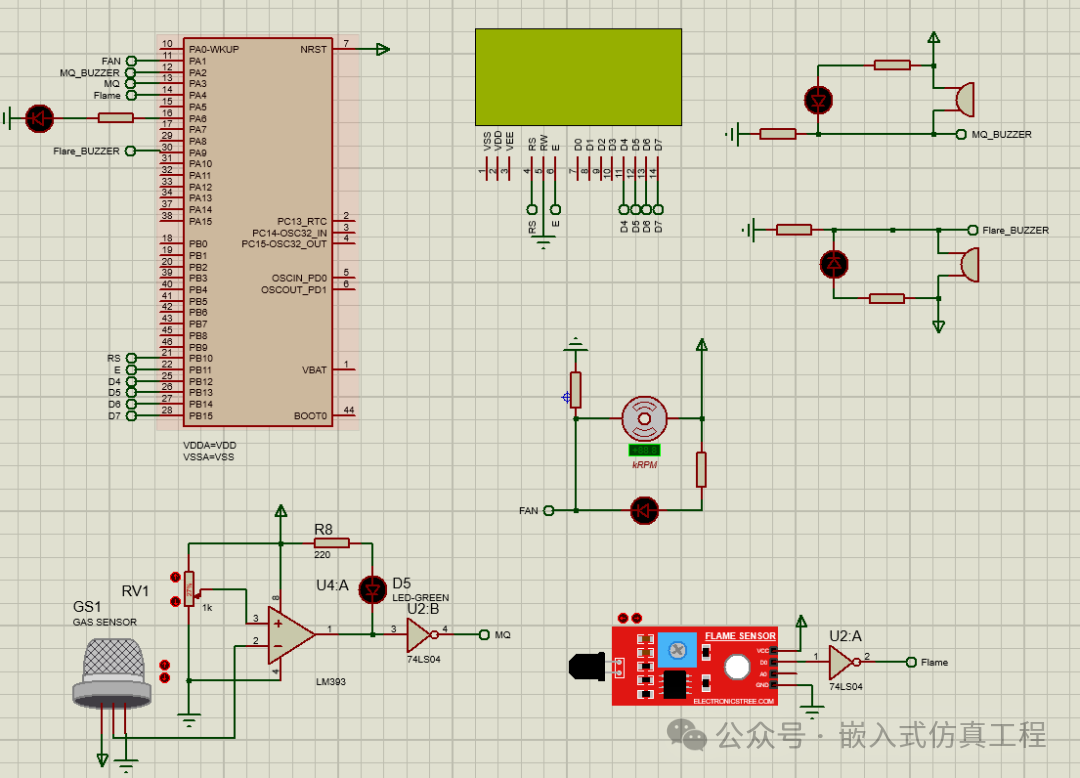
3. Proteus Simulation Instructions
Component List:
-
STM32F103C6
-
LM041L (16×2 LCD)
-
MQ-2 Gas Sensor (simulated with a switch)
-
Flame Sensor (simulated with a switch)
-
Buzzer ×2
-
LED
-
DC Motor (Fan)
-
Resistors, buttons, etc.
Connection Method:
-
PA3: Gas sensor input (connect switch to VCC)
-
PA4: Fire sensor input (connect switch to VCC)
-
PA2: Gas alarm buzzer
-
PA9: Fire alarm buzzer
-
PA1: Fan drive
-
PA6: Gas leak indicator light (LED)
-
PB10-PB15: Connect LCD control lines RS, E and LCD data lines D4, D5, D6, D7.
4. System Functions
-
Normal State: LCD displays“GAS DETECTED: N”,“FAN NOT ACTIVE!”,“FIRE DETECTED: N”, all outputs off
-
Gas Leak: Click the left and right arrows on the GAS sensor to simulate a gas leak, buzzer alarms, fan starts, LED lights up, LCD displays“GAS DETECTED: Y” warning and“FAN ACTIVATED! ” fan activation indication
-
Fire Detection: Click the left and right arrows on the FLAME sensor to simulate a fire alarm, buzzer alarms, LCD displays“FIRE DETECTED: Y” warning
-
Simultaneous Detection: All alarm functions activated
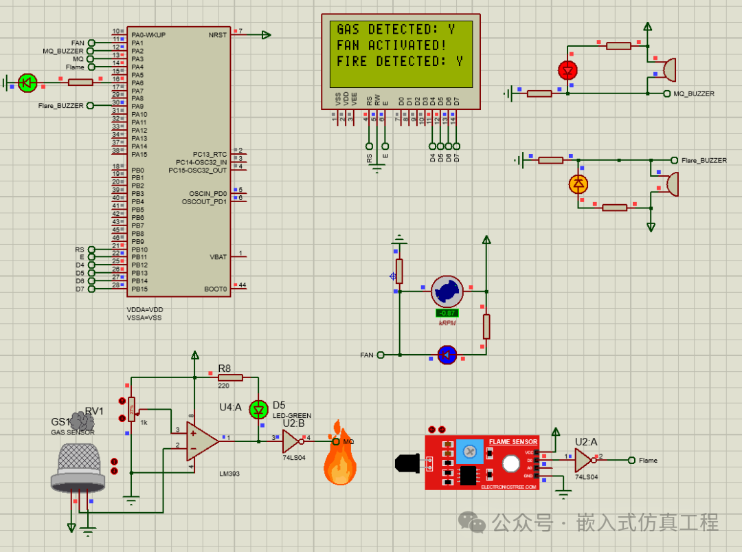
This system provides complete home safety monitoring functions, and the sensor thresholds and alarm logic can be adjusted according to actual needs.
Welcome to follow (operation reference article: Follow the public account and send message operation), click the blue text at the top “Embedded Simulation Project” or long press to identify the QR code to follow
Reply in the public account
3246
After receiving, automatically send the free Keil code project and simulation project link for this project