In some industries, FCS has developed from PLC; in others, FCS has developed from DCS. Therefore, there are intricate connections between FCS, PLC, and DCS, but there are also essential differences.This article analyzes the characteristics and differences of the three major control systems: PLC, DCS, and FCS, pointing out their origins and development directions.
 1
1
PLC, DCS, FCS
Basic Characteristics of the Three Major Control Systems
Currently, in continuous process production automatic control (PA), or commonly referred to as industrial process control, there are three major control systems: PLC, DCS, and FCS. Their basic characteristics are as follows:
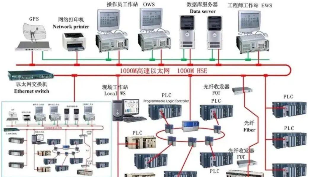
PLC
(1) Develops from switch control to sequential control and transport processing, progressing from the bottom up.
(2) Multifunctionality, including continuous PID control, with PID in the interrupt station.
(3) A PC can be used as the master station, with multiple identical PLCs as slave stations.
(4) One PLC can serve as the master station, with multiple identical PLCs as slave stations, forming a PLC network. This is more convenient than using a PC as the master station because when user programming is involved, there is no need to know the communication protocol; just follow the format in the manual.
(5) The PLC network can serve as an independent DCS/TDCS or as a subsystem of DCS/TDCS.
(6) Large systems can be connected to DCS/TDCS, such as TDC3000, CENTUMCS, WDPFI, MOD300.
(7) PLC networks include Siemens’ SINEC—L1, SINEC—H1, S4, S5, S6, S7, GE’s GENET, and Mitsubishi’s MELSEC—NET, MELSEC—NET/MINI.
(8) Primarily used for sequential control in industrial processes, with new PLCs also incorporating closed-loop control functionality.
(9) Manufacturers: GOULD (USA), AB (USA), GE (USA), OMRON (Japan), MITSUBISHI (Japan), Siemens (Germany), etc.
DCS or TDCS
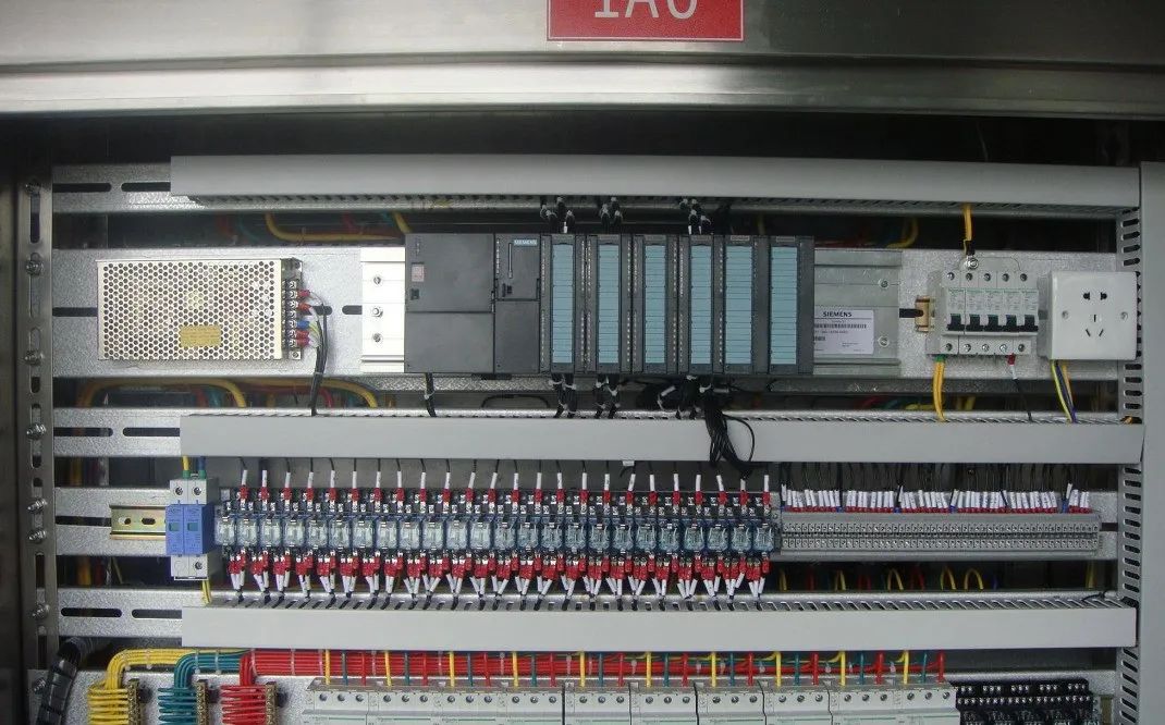
(1) The Distributed Control System (DCS) and the Centralized Control System (TDCS) integrate 4C (Communication, Computer, Control, CRT) technologies into monitoring technology.
(2) A top-down tree topology large system, where communication is key.
(3) PID is in the interrupt station, connecting computers with field instruments and control devices.
(4) It has a tree topology and parallel continuous link structure, with a large number of cables running parallel from relay stations to field instruments.
(5) Analog signals, A/D—D/A, with microprocessor integration.
(6) Each instrument connects to I/O with a pair of wires, linking the control station to the local area network (LAN).
(7) DCS has a three-level structure: control (engineer station), operation (operator station), and field instruments (field measurement and control station).
(8) The disadvantage is high costs, non-interchangeable products from different companies, and non-interoperability; DCS systems are different from each other.
(9) Used for large-scale continuous process control, such as in petrochemicals.
(10) Manufacturers: Bailey (USA), Westinghouse (USA), HITACHI (Japan), LEEDS & NORTHRMP (USA), SIEMENS (Germany), Foxboro (USA), ABB (Switzerland), Hartmann & Braun (Germany), Yokogawa (Japan), Honeywell (USA), Taylor (USA), etc.
FCS
(1) The fundamental task is: intrinsic safety, hazardous areas, variable processes, and challenging environments.
(2) Fully digital, intelligent, multifunctional, replacing analog single-function instruments and control devices.
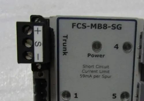
(3) Connects distributed field instruments and control devices, PID, and control center with two wires, replacing two wires for each instrument.
(4) On the bus, PID and instruments, control devices are all equal.
(5) Multivariable, multi-node, serial, digital communication systems replace single-variable, single-point, parallel, analog systems.
(6) Interconnected, bidirectional, open systems replace unidirectional, closed systems.
(7) Uses decentralized virtual control stations instead of centralized control stations.
(8) Operated by field computers, can also connect to upper-level computers on the same bus.
(9) Local area networks can also connect to the internet.
(10) Changes traditional signal standards, communication standards, and system standards into enterprise management networks.
(11) Manufacturers: Honeywell (USA), Smar, Fisher-Rosemount, AB/Rockwell, Elsag-Bailey, Foxboro, Yamatake, Yokogawa (Japan), Siemens (Europe), GEC-Alsthom, Schneider, Process-Data, ABB, etc.
(12) Three typical types of FCS
1) Continuous process automatic control, such as petrochemicals, where “intrinsically safe explosion-proof” technology is absolutely crucial, typical products include FF, World FIP, Profibus-PA;
2) Discrete process automatic control, such as automotive manufacturing robots, typical products include Profibus-DP, CANbus;
3) Multi-point control, such as building automation, typical products include LON Work, Profibus-FMS.
From the description of the basic points above, have we noticed that none of the three major systems used for process control were developed specifically for power plants? Or rather, at the initial stage of their development, they were not primarily aimed at power plants as the preferred control object. Moreover, in the usage instructions of these systems, power plants are never mentioned as the preferred applicable scope; some do not even mention power plants at all.
Now it is strange that these three major control systems, especially DCS and PLC, have been widely used in power plants, and the results are very good.
2Differences Between the Three Major Control Systems
We already know that FCS developed from DCS and PLC, and FCS not only possesses the characteristics of DCS and PLC but also takes a revolutionary step beyond. Currently, new types of DCS and PLC are trending towards each other.
New types of DCS have strong sequential control functions; new types of PLC are also competent in handling closed-loop control, and both can form large networks, with significant overlap in the applicability of DCS and PLC.The next section will compare DCS and FCS. The differences between DCS and FCS have already been touched upon in previous chapters; the following will describe aspects such as architecture, investment, design, and usage.
Key Differences
The key to DCS systems is communication. It can also be said that the data highway is the backbone of the distributed control system DCS. Since its task is to provide a communication network between all components of the system, the design of the data highway itself determines the overall flexibility and safety. The media for the data highway can be: a pair of twisted wires, coaxial cables, or fiber optic cables.
Through the design parameters of the data highway, one can fundamentally understand the relative advantages and disadvantages of a specific DCS system.
(1) How much I/O information can the system handle. (2) How much control loop information related to control can the system handle. (3) How many users and devices (CRT, control stations, etc.) can it accommodate. (4) How thoroughly the integrity of transmitted data is checked. (5) What is the maximum allowable length of the data highway. (6) How many branches can the data highway support. (7) Whether the data highway can support hardware produced by other manufacturers (programmable controllers, computers, data recording devices, etc.).
To ensure the integrity of communication, most DCS manufacturers can provide redundant data highways.
To ensure system safety, complex communication protocols and error-checking techniques are employed. The so-called communication protocol is a set of rules to ensure that transmitted data is received and understood in the same manner as the sent data.
Currently, DCS systems generally use two types of communication methods, namely synchronous and asynchronous; synchronous communication relies on a clock signal to regulate data transmission and reception, while asynchronous networks use a non-clock reporting system…
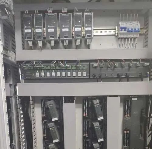
Key Points of FCS
(1) The Core of FCS System
The core of the FCS system is bus protocol; once its bus protocol is determined, the relevant key technologies and associated devices are also determined. In terms of the basic principles of its bus protocol, various buses are the same, all based on solving bidirectional serial digital communication transmission. However, due to various reasons, the bus protocols of different types of buses vary significantly.
To meet interoperability requirements for field buses and make them true open systems, the IEC international standard clearly states that the user layer of the field bus communication protocol model must have device description functionality.
To achieve interoperability, each field bus device is described using a device description (DD). DD can be thought of as a driver for the device, including all necessary parameter descriptions and operational steps required by the master station. Since DD includes all the information needed to describe the device’s communication and is independent of the master station, it enables true interoperability of field devices.
It contains 8 types, while the original IEC international standard is just one of the 8 types, with the other 7 types of buses being equal in status. Each of the other 7 buses, regardless of their market share, has a complete set of software and hardware support. They can form systems and products, while the original IEC field bus international standard is an empty framework without software or hardware support.
Therefore, achieving mutual compatibility and interoperability among these buses, given the current state, is nearly impossible.
From the above, can we draw the impression that: the interoperability of open field bus control systems, for a specific type of field bus, as long as the bus protocol of that type is followed, the products are open and possess interoperability.
In other words, regardless of the manufacturer, as long as the product adheres to the bus protocol, products are open and possess interoperability, allowing them to form a bus network.
(2) The Foundation of FCS System is Digital Intelligent Field Devices
Digital intelligent field devices are the hardware support for the FCS system and its foundation. The reasoning is simple: the FCS system executes bidirectional digital communication field bus signals between automatic control devices and field devices.
If the field devices do not adhere to a unified bus protocol, i.e., relevant communication protocols, and do not have digital communication capabilities, then so-called bidirectional digital communication is meaningless and cannot be termed a field bus control system.
Additionally, a major characteristic of field buses is to enhance field-level control functions. If field devices are not multifunctional and intelligent products, then the characteristics of the field bus control system will not exist, and the advantages of simplifying systems, facilitating design, and aiding maintenance will also be illusory.
(3) The Essence of FCS System is Information Processing at the Field Level
For a control system, whether using DCS or field buses, the amount of information that the system needs to process is at least the same.In fact, using field buses allows for obtaining more information from the field.
The amount of information in a field bus system is not reduced; it may even increase, while the cables for transmitting information are significantly reduced. This requires, on one hand, a significant increase in the capability of cables to transmit information, and on the other hand, to allow a large amount of information to be processed on-site, reducing the back-and-forth information flow between the field and control room. It can be said that the essence of field buses is the localization of information processing.
Reducing information back-and-forth is an important principle in network design and system configuration. Reducing information back-and-forth often brings benefits in improving system response time. Therefore, when designing networks, nodes that exchange large amounts of information should be prioritized to be placed on the same branch.
Reducing information back-and-forth and reducing the number of cables in the system can sometimes contradict each other. In such cases, the principle of saving investment should be chosen. If the selected system’s response time allows, a solution that saves cables should be chosen. If the selected system’s response time is tight, a slight reduction in information transmission will suffice, then a solution that reduces information transmission should be chosen.
Currently, some field instruments with field buses have many function blocks built into them; although different products have slight differences in performance, the existence of many identical function blocks on a network branch is an objective reality. Choosing which function block on which field instrument is a problem to be solved in system configuration.
The principle for considering this issue is: to minimize information back-and-forth on the bus. Generally, the function block on the instrument with the most information output related to that function should be selected.
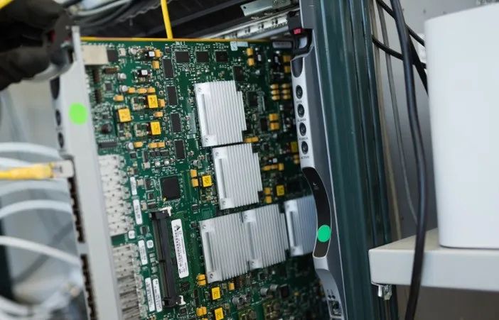
Typical System Comparison
By using field buses, users can significantly reduce field wiring; a single field instrument can achieve multivariable communication, and devices produced by different manufacturers can fully interoperate, enhancing field-level control functions, greatly simplifying system integration, and making maintenance very convenient.
In traditional process control instrument systems, each field device requires a dedicated pair of twisted wires to transmit 4-20mA signals to the control room; in field bus systems, each field device can still use twisted wires to the junction box, but only one twisted wire is needed from the field junction box to the central control room for digital communication.
The exact amount of cable saved by adopting field bus control systems has not been calculated by the author. However, based on the number of kilometers of cable used in power plants with DCS systems related to automatic control systems, we can see the share of cable in infrastructure investment.
In a certain power plant, 2×300MW coal-fired units are set up. The thermal system is unit-based. Each unit is equipped with a centralized control building, adopting centralized control of machine, furnace, and electricity units. The elevation of the unit control room is 12.6 meters, consistent with the operating layer elevation. DCS uses WDPF—Ⅱ, with a designed I/O point of 4500 points.
Cable laying uses EC software; 8 people took 1.5 months to complete the cable laying design task; in the main plant, the number of cables for each 300MW unit in automation specialty is 4038 cables; the length of cables for each 300MW unit in automation specialty is 350 kilometers; the above numbers do not include the fire alarm power cables for the entire plant and the cables for all auxiliary production workshops; the cable tray columns, trays, and small troughs are all made of galvanized steel, weighing about 95 tons for each unit.
Other cable trays include straight-through, bends, tees, crosses, covers, terminal caps, widening pieces, and direct pieces, made of aluminum alloy, weighing about 55 tons for each 300MW unit. Accessories such as bolts and nuts are provided with the trays.
In another power plant, 4×MW oil and gas power station is set up. The thermal system is unit-based. DCS uses TELEPERM-XP, with a designed I/O point number of 5804 points.
Cable laying uses EC software; 12 people took 2.5 months to complete the cable laying design task; in the main plant, the number of cables for each 325MW unit in automation specialty is 4413 cables; the length of cables for each 235MW unit in automation specialty is 360 kilometers; all units use galvanized steel cable trays, weighing about 200 tons each.
The power plant cables can be divided into six major categories: high-voltage power cables, low-voltage power cables, control cables, thermal control cables, weak current cables (mainly referring to computer cables), and other cables.
If two 300MW units lay cables simultaneously, the number of automation specialty cables is approximately 8500. Among them, thermal control cables and weak current cables will exceed 5000, accounting for about 60% (measured by quantity).
Design, Investment, and Use
The above comparison focuses on purely technical aspects; the following comparison will include economic factors.
The premise of the comparison is to compare the DCS system with a typical, ideal FCS system. Why make such an assumption? As DCS systems have developed to today, the technical requirements proposed in the early development stages have been met and improved, and the current situation is to further enhance, thus there is no typical or ideal description.

As for the FCS system, it only entered practical use in the 1990s. The technical requirements proposed in its early development stages include: compatibility and openness, bidirectional digital communication, digital intelligent field devices, high-speed buses, which are still not ideal and need improvement. This state is not unrelated to the formulation of international standards for field buses. Over the past decade, various bus organizations have been busy formulating standards, developing products, and capturing more market share, aiming to gain a foothold in international standards to legally occupy a larger market.
Now that the battle over international standards has come to a pause, major companies have realized that to truly capture the market, they need to improve systems and related products. We can predict that in the near future, a perfected field bus system and related products will become the mainstream of global field bus technology.
Specific Comparisons:
(1) The DCS system is a large system, with powerful controller functions that play a crucial role in the system, and the data highway is the key to the system. Therefore, a comprehensive investment must be made all at once, and subsequent expansion is quite challenging. In contrast, the FCS has thoroughly decentralized functions, information processing at the field level, and the widespread adoption of digital intelligent field devices reduces the importance of controller functions. Thus, the FCS system has a low investment threshold, allowing for gradual use, expansion, and commissioning.
(2) The DCS system is a closed system; products from different companies are generally incompatible. In contrast, the FCS system is an open system, allowing users to connect various devices from different manufacturers and brands to the field bus, achieving optimal system integration.
(3) The information in DCS systems is all formed from binary or analog signals, requiring D/A and A/D conversion. Meanwhile, the FCS system is fully digital, eliminating the need for D/A and A/D conversion, resulting in high integration and performance, improving accuracy from ±0.5% to ±0.1%.
(4) The FCS system can embed PID closed-loop control functions into transmitters or actuators, shortening control cycles, currently improving from DCS’s 2-5 times per second to FCS’s 10-20 times per second, thereby enhancing regulation performance.
(5) DCS can control and monitor the entire process, perform diagnostics, maintenance, and configuration on itself. However, due to its fatal weakness, its I/O signals use traditional analog signals, making it impossible to perform remote diagnostics, maintenance, and configuration on field instruments (including transmitters, actuators, etc.) from the DCS engineer station.
(6) Due to information processing at the field level, the FCS can save a considerable number of isolators, terminal cabinets, I/O terminals, I/O cards, I/O files, and I/O cabinets compared to DCS. Experts believe that this can save up to 60%.
(7) For the same reasons as (6), the FCS can significantly reduce the number of cables and cable trays used for laying cables, while also saving design, installation, and maintenance costs. Experts believe that this can save up to 66%. For points (6) and (7), it should be noted that while the investment savings from adopting the FCS system are undeniable, whether they reach the 60-66% claimed by some experts is still uncertain. These numbers have appeared in multiple articles, and the author believes they may be a result of mutual citation; thus, readers should be cautious when quoting these figures.
(8) The FCS is simpler to configure compared to DCS, due to its structure and performance standardization, making installation, operation, and maintenance easier.
(9) The design and development key points for FCS used in process control are not meant to compare with DCS; they are simply to highlight issues that should be considered in the design and development of FCS used for process control or for simulating continuous processes.
3Prospects of PLC and DCS
We already know that some FCS have developed from PLC, while others have developed from DCS. Now that FCS has become practical, what will the prospects of PLC and DCS be?
PLC first appeared in the late 1960s in the USA, designed to replace relays and perform logic, timing, counting, and other sequential control functions, establishing flexible program control systems.
In 1976, it was officially named and defined: PLC is a specialized digital control electronic computer that uses programmable memory to store instructions, executing functions such as logic, sequencing, timing, counting, and calculations through analog and digital input and output components to control various machinery or work programs.After more than 30 years of development, PLC has matured and improved, and has developed analog closed-loop control functionality.
The position of PLC in the FCS system seems to have been established without much debate.PLC acts as a station on a high-speed bus, fully leveraging its advantages in handling switch quantities.
Additionally, auxiliary workshops in thermal power plants, such as makeup water treatment workshops, circulating water workshops, ash and slag removal workshops, and coal conveying workshops, mainly focus on sequential control processes. PLC has unique advantages for sequential control.
The control systems for auxiliary workshops should preferably use PLCs that comply with field bus communication protocols or can communicate with FCS to exchange information.
Disclaimer: The articles uploaded by this WeChat public account only represent the author’s views, and the copyright belongs to the original author. If there are errors in the source of the article or issues related to copyright, please inform, and the editor will delete it promptly.
Editor: Wei Xing | Reviewer: Chen Liang | Supervising Review: Wen Hui

Click the blue text to follow us