Modbus to Profinet Gateway Connecting Configuration Case of TP613 Three-Phase Smart Power Meter and PLC
The Modbus to Profinet protocol conversion technology innovatively transforms traditional production modes through a conversion mechanism, enabling data communication between Programmable Logic Controllers (PLC) and measuring instruments. This innovative field application solution effectively resolves communication barriers between PLCs and measuring instruments, ensuring high-speed data transmission and more accurate data collection.
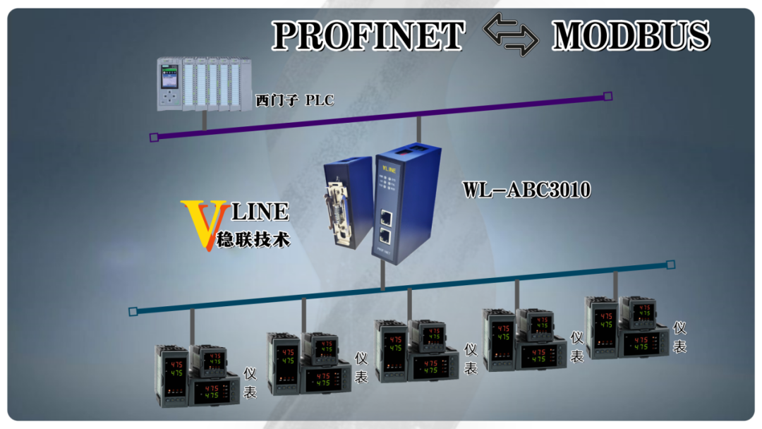
This case study explores the connection configuration of the TP613 three-phase smart power meter and PLC through the Modbus to Profinet gateway. The devices involved in the study include the Siemens S7-1200 PLC, Modbus to Profinet gateway, and TP613 three-phase smart power meter. The research steps first involve starting the PLC control software and adding the GSD file. After installation, the Modbus to Profinet gateway module must be located at the specified address.
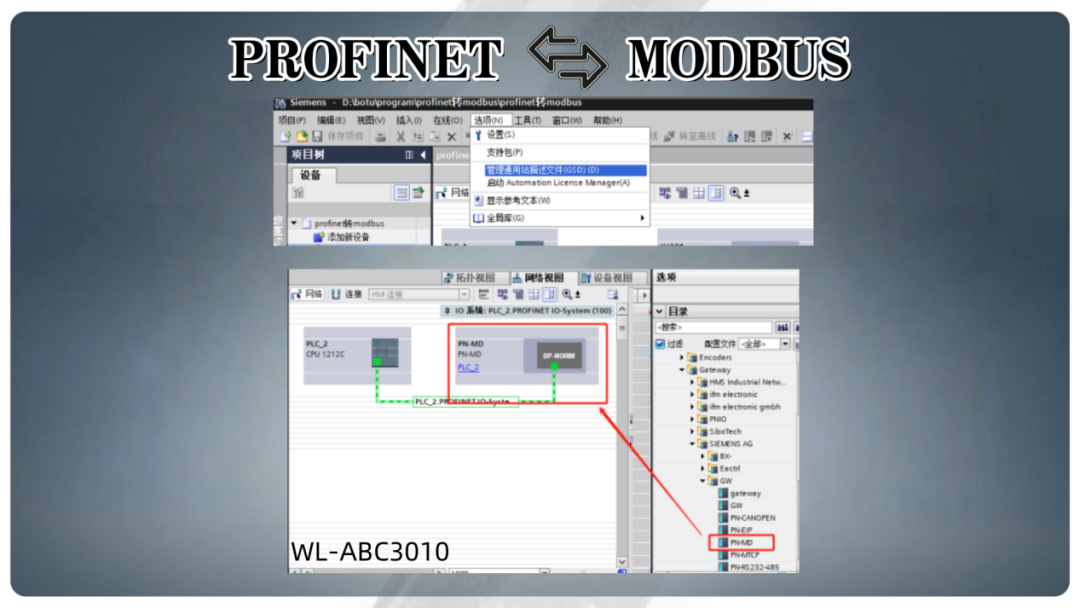
During the configuration process of the Modbus to Profinet gateway, it is essential to ensure that the gateway’s IP address, the Programmable Logic Controller (PLC) address, and the computer’s IP address are all within the same network segment. Locate the hardware directory in the device view and add the read/write data length.
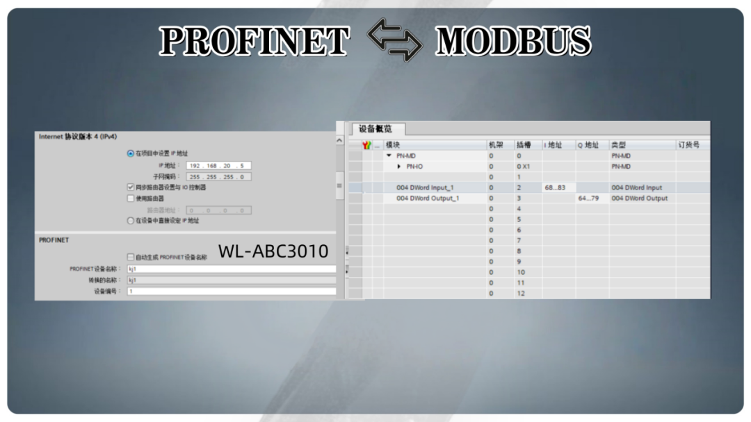
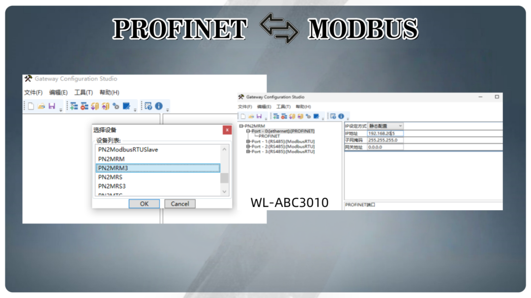
At this stage, the Modbus to Profinet gateway configuration software must be installed. After opening the software, create a new project and select PN2MRM3. First, the IP address and device name of the PN side must be configured to ensure they match exactly with the configuration in the Profinet system.
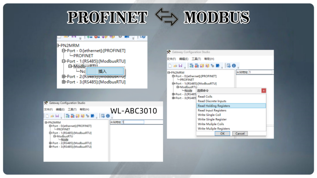
Right-click on the Modbus RTU, select insert node, and fill in the slave address in the node address bar. If there is any doubt about the accuracy of the selection, it is recommended to verify in the function code area on the right.
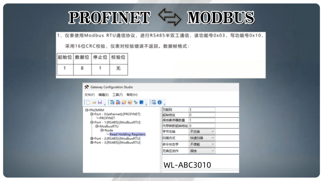
As shown in the figure, the communication application format related instructions for the Modbus slave are specified. According to the case analysis, when the Modbus protocol slave address is set to 1, the function code is set to 03, and two registers are specified for reading, the configuration process of the Modbus to Profinet gateway can be initiated. In the example provided in the manual, the starting address is represented in hexadecimal as 006CH, which needs to be converted to decimal value 108 to read the data of the two registers continuously starting from that address. This data should then be accurately filled into the corresponding chart.
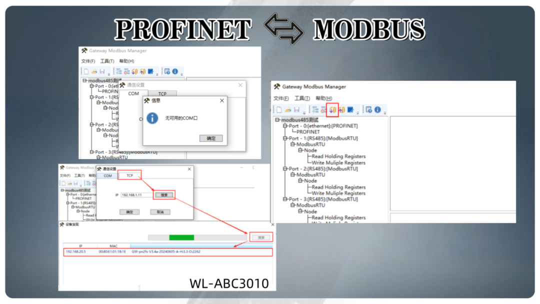
After completing the configuration of all required parameters, execute the download operation, then click on tools and communication settings in sequence. When the “No available COM port” prompt appears, click “OK”. Select TCP, and perform an IP search for the Modbus to Profinet gateway. In the set of Modbus to Profinet gateway IPs obtained from the search, double-click the target IP to initiate the download process.
By integrating the Programmable Logic Controller (PLC) with the Modbus to Profinet gateway, interoperability conversion between different communication protocols of industrial production equipment has been achieved. Furthermore, by finely configuring the Modbus to Profinet gateway, users can efficiently adjust communication parameter settings, ensuring stability and continuity in the industrial production site.