The various states of the servo amplifier are managed by the state machine shown in the figure below. The state of the slave (servo amplifier) will change based on the control command (6040h) from the master (controller). Additionally, the current state of the servo amplifier can be read through the control status (6041h).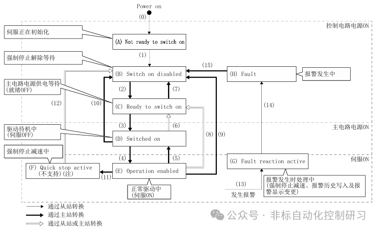 The key registers used are two:
| Address | Name | Data Type | Read/Write | No. of Points/ No. of Registers |
| 6040H | Control Command | 2 bytes | Read/Write | 1 |
| 6041H | Control Status | 2 bytes | Read | 1 |
Details on the usage of these two registers:Control Command: 6040H → Sends commands from the master (controller) to the slave (servo amplifier). Read/Write operations are possible.When using function code “03H” to read holding registers, the current state of the control command can be confirmed.When using function code “10H” to write multiple holding register data, control commands can be written to the servo amplifier.The meaning of each bit in this register is as follows:
| Bit | Content | Remarks |
| 0 | Switch On | |
| 1 | Enable Voltage | |
| 2 | Quick Stop | |
| 3 | Enable Operation | |
| 4-6 | Operation Mode Specific | Changes based on control mode |
| 7 | Fault Reset | |
| 8 | Halt | |
| 9-15 | Reserved |
For example, in the home position reset mode, the meaning of bit 4 changes to “Start Home Position Reset”. When starting the home position reset, bit 4 is changed from “0” to “1”. After the home position reset is completed or an alarm occurs during the reset, bit 4 needs to be changed from “1” to “0”.If bit 8 (Halt) in the control command (6040h) is set to “1”, the servo motor will decelerate to a stop. Then, after setting bit 8 (Halt) to “0” and returning bit 4 to “0”, if it is changed to “1”, the home position reset will be performed again.The other control status register: 6041H
| Address | Name | Data Type | Read/Write | No. of Points/ No. of Registers |
| 6041H | Control Status | 2 bytes | Read | 1 |
Detailed explanation of each bit:
| Bit | Content | Remarks |
| 0 | Ready To Switch On | Servo Initialization |
| 1 | Switched On | Drive Standby |
| 2 | Operation Enabled | Servo ON |
| 3 | Fault | Alarm |
| 4 | Voltage Enabled | |
| 5 | Quick Stop | Emergency Stop |
| 6 | Switch On Disabled | Forced Stop Release Waiting |
| 7 | Warning | |
| 8 | Reserved | Related to control mode |
| 9 | Remote | |
| 10 | Target reached | |
| 11 | Internal Limit Active | |
| 12-13 | Operation Mode Specific | |
| 14-15 | Reserved | Related to control mode |
This register address has read-only permission, using function code “03H”..Note: In Modbus-RTU communication, when the control command (Controlword) is valid, bit 9 becomes ON. When the travel limit, software limit, and position command are out of range, bit 11 becomes ON.When controlling, it is necessary to first confirm the control mode: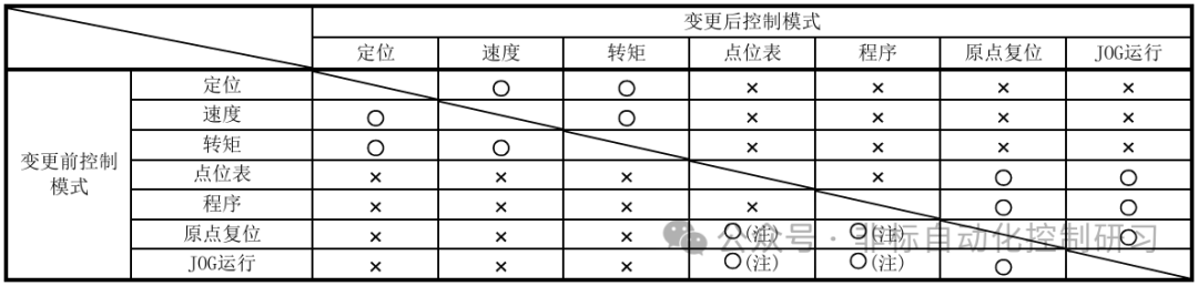 O: Switchable : Not Switchable Note: For switching between the position table and the program, please set through [Pr.PA01].After switching the control mode, you can confirm that the control mode has been switched through the control mode display (Modes of operation Display: 6061h). Please switch the control mode when the servo motor is stopped.
| Address | Name | Data Type | Read/Write | No. of Points/ No. of Registers |
| 6060H | Control Mode | 1 byte | Read/Write | 1 |
| 6061H | Control Mode Display | 1 byte | Read | 1 |
| 6502H | Supported Control Modes | 4 bytes | Read | 2 |
6060H: Control Mode RegisterWhen using function code “03h” to read holding registers, confirm the current setting value of the control mode.When using function code “10h” to write multiple holding register data, the control mode can be set to switch modes. Mode setting rules:
| Control Mode | Setting Value |
| Position Control | -20 |
| Speed Control | -21 |
| Torque Control | -22 |
| Position Table | -101 |
| Program Run | -102 |
| Home Position Mode | 6 |
| JOG Operation | -100 |
What does this mean? For example, a command[ADPRW 01H 10H 6060H 1H D30 M30 ]The register write command runs, writing the value from D30 into the control mode register address 6060H. When (D30)=-100, the current control mode switches to JOG operation.After the mode change, the mode can be confirmed through register: 6061H to see if the switch was successful.
| Control Mode | Setting Value |
| Position Mode | -20 |
| Speed Control | -21 |
| Torque Control | -22 |
| Position Table | -101 |
| Program Run | -102 |
| Home Position Reset | 6 |
| JOG Operation | -100 |
| Trial Run Mode: JOG Operation | -1 |
| Trial Run Mode: Positioning Operation | -2 |
| Trial Run Mode: DO Forced Output | -4 |
| Trial Run Mode: Mechanical Analyzer | -6 |
| Trial Run Mode: 1 Step Feed (when running position table) | -10 |
| Trial Run Mode: 1 Step Feed (when running program) | -11 |
Using function code “03h” to read holding registers, the read value can be compared to confirm the current mode setting state.