 Above is an advertisement The following video is sourced from Zheng Movement Assistant
The electronic gear mode can link two or more axes together to achieve precise synchronous motion, thus replacing traditional mechanical gear connections.
The axis being followed is called the master axis, while the following axis is the slave axis. By connecting the slave axis to the master axis at a certain ratio, when the master axis moves, the connected slave axis also moves accordingly. The number of pulses connected must consider the ratio of different axis UNITS.
First
Part
Function of Electronic Gears
1. Pulse compensation reduces the burden on the upper computer (as the current pulse sending components have frequency limits for sending pulses).2. Matches the number of pulses emitted by the motor with the minimum mechanical movement amount, allowing the input command for one pulse to correspond to any value of workpiece (or motor) movement; it enables stepless speed regulation of the motor, preventing loss of steps and overshooting during motor startup and shutdown, thus maximizing the potential of the motor.3. Transfers synchronous motion information, achieving coordinated movement and transformation between motion forms (rotation-rotation, rotation-linear, linear-linear), simplifying control, etc.
Second
Part
Electronic Gear Command Description
1.CONNECT Synchronous Motion
|
Type |
Synchronous motion command |
|
Description |
Connects the target position of the current axis with the measured position of the driving_axis through electronic gears. The number of pulses connected must consider the ratio of different axis UNITS. To disconnect, use CANCEL. Assuming the UNITS of connected axis 0 is 100, and the UNITS of connected axis 1 is 10. When using CONNECT, if the ratio is 1, then CONNECT(1,0) AXIS(1) When axis 0 moves s1=100, axis 1 moves = s1*UNITS(0)*ratio/UNITS(1), resulting in a movement of 1000. The ratio can dynamically change through repeated command calls. This is commonly used with handwheels. |
|
Syntax |
CONNECT(ratio, driving_axis) ratio: The ratio, can be positive or negative, note that it is the ratio of pulse counts driving_axis: The axis number of the connected axis, for handwheels it is the encoder axis |
|
Applicable Controllers |
Universal |
2.CONNPATH Synchronous Motion 2
|
Type |
Synchronous motion command |
|
Description |
Connects the target position of the current axis with the interpolated vector length of the driving_axis through electronic gears. The number of pulses connected must consider the ratio of different axis UNITS. To disconnect, use CANCEL. The ratio can dynamically change through repeated command calls. |
|
Syntax |
CONNPATH(ratio, driving_axis) ratio: The ratio, can be positive or negative, note that it is the ratio of pulse counts driving_axis: The axis number of the connected axis, for handwheels it is the encoder axis |
|
Applicable Controllers |
Universal |
3.CANCEL Single Axis Stop/Axes Group Stop
|
Type |
Single axis motion command |
|
Description |
BASE axis deceleration stop, if the axis is involved in interpolation, it also stops the interpolation motion. If the specified axis is in the BASE axis list, regardless of whether it is CANCELing the master axis or the axes in the BASE axis list, it stops the interpolation motion of the axis group. The deceleration for MODE0~2 is based on the maximum value of FASTDEC and DECEL. After CANCEL, to call absolute position motion, you must first WAIT IDLE until the stop is complete. |
|
Syntax |
CANCEL(mode) mode: mode selection |
|
Applicable Controllers |
Universal |
4.Electronic Gear Usage Example
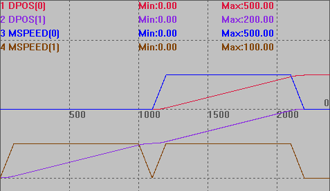
RAPIDSTOP(2)WAIT IDLE(0)WAIT IDLE(1)BASE(0,1)ATYPE=1,1UNITS=100,1000DPOS=0,0SPEED=100,100ACCEL=1000,1000DECEL=1000,1000TRIGGER 'Automatic trigger oscilloscopeMOVE(100) AXIS(1) 'Axis 1 moves 100, while axis 0 does not moveWAIT IDLE(1) 'Previous motion not connectedCONNECT(0.5,1) AXIS(0) 'Axis 0 connected to axis 1, ratio is 0.5'CONNPATH(0.5,1) AXIS(0) 'Axis 0 connected to axis 1, ratio is 0.5MOVE(100) AXIS(1) 'Axis 1 moves 100, axis 0 moves distance: 100*1000*0.5/100=500Routine running effect:
5.Command Precautions
CONNECT-synchronous motion and CONNPATH-synchronous motion 2 are both electronic gear connection commands, and their usage syntax rules are the same.
CONNECT connects the measured length, the number of pulses emitted by the master axis * connection ratio = the number of pulses emitted by the slave axis, meaning that under the same connection ratio, the number of pulses emitted by the master axis equals the number of pulses emitted by the slave axis.
CONNPATH connects the interpolated vector length, the number of pulses emitted by the composite axis * connection ratio = the number of pulses emitted by the slave axis, meaning that under the same connection ratio, the number of pulses emitted by the master axis and other axes in composite motion equals the number of pulses emitted by the slave axis.
If CONNPATH connects to a single axis, its motion effect is the same as CONNECT.
Third
Part
Electronic Gear Application Cases
1.Controller Schematic
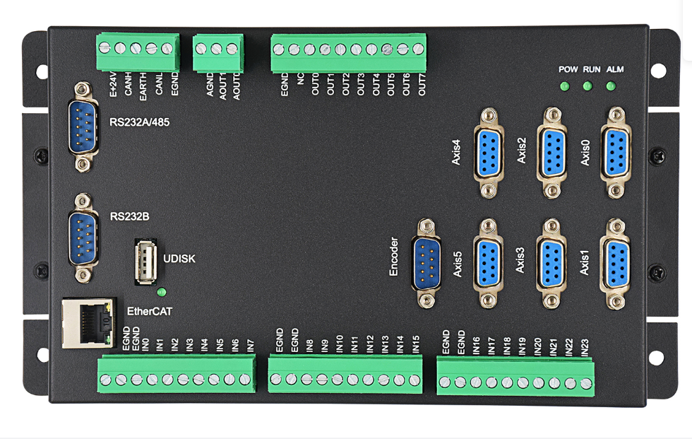 ZMC006CE handwheel interface (Encoder) schematic
|
Handwheel axis pin number |
Pin function |
Handwheel axis pin number |
Pin function |
Handwheel axis pin number |
Pin function |
|
1 |
EA+ |
4 |
EB- |
7 |
EZ- |
|
2 |
EA- |
5 |
GND |
8 |
5V |
|
3 |
EB+ |
6 |
EZ+ |
9 |
/ |
Handwheel axis pin description2.Handwheel Schematic
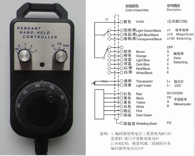
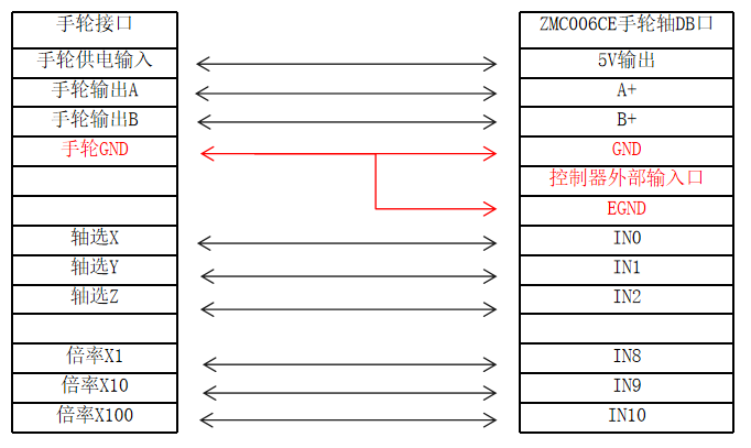
3.Handwheel Wiring withZMC006CE Handwheel Axis
4.Handwheel Position Compensation – Ladder Diagram Example
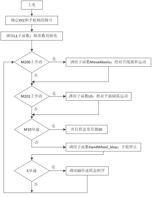
Ladder diagram program structure: After powering on, it continuously scans to determine the state of auxiliary relay M, thereby calling different subprograms to execute.
The state of auxiliary relay M is controlled by the HMI interface.
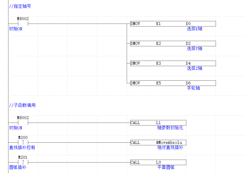
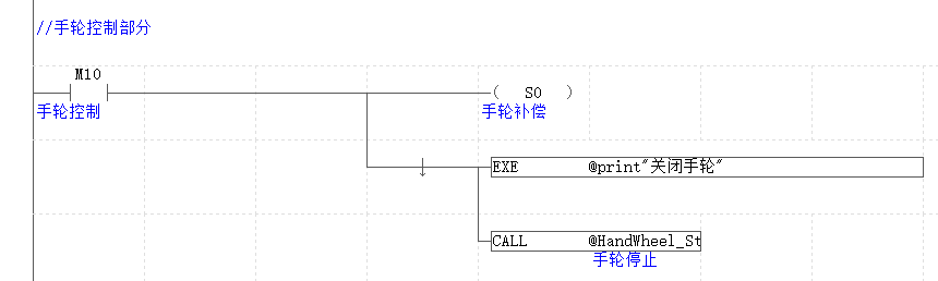
Handwheel application ladder diagram program:
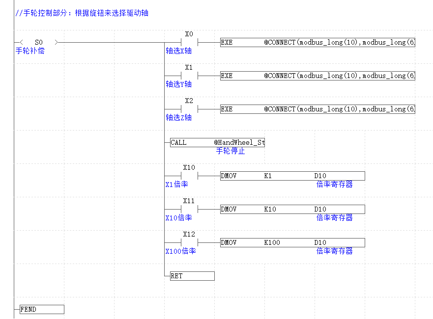
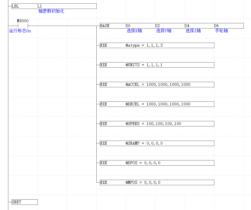
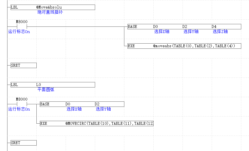
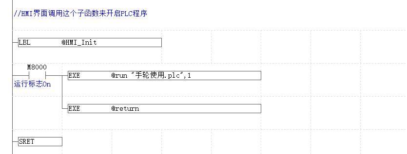
The following sub-function is unrelated to the main program, its role is to start the PLC file task during the HMI initialization function. The above PLC file is activated by the automatic running task number. If the PLC file is not set to run automatically, the following program can be called.
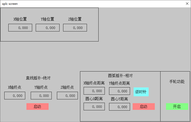
Handwheel application case interface effect
The following video is sourced from Zheng Movement Assistant
//Specify axis numberld m8002DMOV K1 D0DMOV K2 D2DMOV K3 D4DMOV K5 D6//Sub-function callld m8002CALL L1LDP M200CALL @MoveAbsoluLDP M201CALL L0//Handwheel control partLD M10out s0edexe @print"Close Handwheel"call @HandWheel_Stop//Handwheel control part: Select driving axis and connection ratio based on the knobSTL S0MPSAND X0EXE @CONNECT(modbus_long(10),modbus_long(6)) AXIS(modbus_long(0))MRDAND X1EXE @CONNECT(modbus_long(10),modbus_long(6)) AXIS(modbus_long(2))MRDAND X2EXE @CONNECT(modbus_long(10),modbus_long(6)) AXIS(modbus_long(4))MRDcall @HandWheel_StopAND X10DMOV K1 D10MRDAND X11DMOV K10 D10MPPAND X12DMOV K100 D10RETfend//In different situations, this sub-function determines whether to stop handwheel functionlbl @HandWheel_Stopldi x0ANI X1ANI X2ORP X0ORP X1ORP X2ORI S0Base d0exe @CANCEL(0)Base d2exe @CANCEL(0)base d4exe @CANCEL(0)sret//Initialize selected axislbl l1ld m8000BASE D0 D2 D4 D6 EXE @atype = 1,1,1,3EXE @UNITS = 1,1,1,1EXE @ACCEL = 1000,1000,1000,1000EXE @DECEL = 1000,1000,1000,1000EXE @SPEED = 100,100,100,100EXE @SRAMP = 0,0,0,0EXE @DPOS = 0,0,0,0EXE @MPOS = 0,0,0,0sretLBL @MoveAbsoluld m8000base d0 d2 d4exe @moveabs(TABLE(0),TABLE(2),TABLE(4))sretLBL l0 ld m8000base d0 d2 exe @MOVECIRC(TABLE(10),TABLE(11),TABLE(12),TABLE(13),MODBUS_BIT(100))sretThis concludes the EtherCAT motion controller PLC programming (Part 3) – Electronic Gears. For more exciting content, please follow the “Zheng Movement Assistant” public account. If you need the relevant development environment and example code, please consult Zheng Movement’s sales engineer:400-089-8936.
This article is original from Zheng Movement Technology, and everyone is welcome to share and learn together to improve China’s intelligent manufacturing level. The copyright of the article belongs to Zheng Movement Technology. If reprinted, please indicate the source.
Review Previous Content
EtherCAT Motion Controller PLC Programming (Part 2) Arc Interpolation
EtherCAT Motion Controller PLC Programming (Part 1) Linear Interpolation
EtherCAT Motion Control Card Motion Pause, Resume, and System Safety Settings
EtherCAT Motion Control Card Small Segment Foreseeing Continuous Interpolation Motion
EtherCAT Motion Control Card Multi-Axis Interpolation Motion and Handwheel Motion
EtherCAT Motion Control Card Auxiliary Debugging Tools and Methods Introduction
EtherCAT Motion Control Card Bus Axis Parameter Settings and Axis Motion
EtherCAT Motion Control Card Hardware Wiring and C# Single Axis Motion ControlEtherCAT Motion Control Card Hardware Wiring and C# Hardware Peripheral Read and Write and Return to Zero MotionEtherCAT Motion Control Card Bus Axis Parameter Settings and Axis Motion
About Zheng Movement Technology
Zheng Movement Technology focuses on the research of motion control technology and the development of general motion control software and hardware products, it is a national high-tech enterprise, with main products including motion controllers, motion control cards, machine vision motion control integrated machines, human-computer interfaces, and expansion modules.
Zheng Movement Technology gathers outstanding talents from companies such as Huawei and ZTE, actively collaborates with major universities to research basic technologies of motion control while adhering to independent innovation, and is one of the fastest-growing enterprises in the domestic industrial control field, as well as one of the few enterprises that fully master core motion control technologies and real-time industrial control software platform technologies.
 – END –
Popular Articles

Linear Motor Fifteen Years
Third Batch of Specialized, Refined, Unique, and Innovative “Little Giant” Enterprises
Xiaomi Launches Robot Dog for Just 9999
Yaskawa Launches Custom Servo Products