Reading this article will take about 14 minutes.
Source: Ruan Yifeng, link: http://www.ruanyifeng.com/blog/2012/05/internet_protocol_suite_part_i.html
Before writing:
This article provides a comprehensive overview of the TCP/IP network protocols, making it excellent introductory material for beginners. Professionals can also use it to fill in gaps, and it’s suitable for last-minute preparation for interviews. Additionally, I have two books related to networking: “Computer Networks (Xie Xiren Edition)” and “Understanding Linux Network Technology Inside Out”. Those interested can reply with “Network” in the background.
00 Preface
We use the internet every day; have you ever wondered how it works?
Billions of computers worldwide are connected, communicating with each other. A network card in Shanghai sends a signal, and another network card in Los Angeles receives it, without either knowing the other’s physical location. Isn’t that amazing?
The core of the internet consists of a series of protocols collectively known as the “Internet Protocol Suite”. They provide detailed specifications on how computers connect and form networks. Understanding these protocols means understanding the principles of the internet.
Below are my study notes. Because these protocols are incredibly complex and vast, I wanted to organize a simple framework to help myself grasp them overall. To ensure simplicity and clarity, I made many simplifications; some areas may not be comprehensive or accurate, but they should clarify the principles of the internet.
01 Overview
1.1 Five-Layer Model
Implementing the internet is divided into several layers. Each layer has its own functions, much like a building where each floor is supported by the one below it.
Users only interact with the top layer and are unaware of the layers below. To understand the internet, one must start from the bottom layer and understand the functions of each layer from the ground up.
There are different models for layering; some models divide it into seven layers, while others into four. I think dividing the internet into five layers makes it easier to explain.
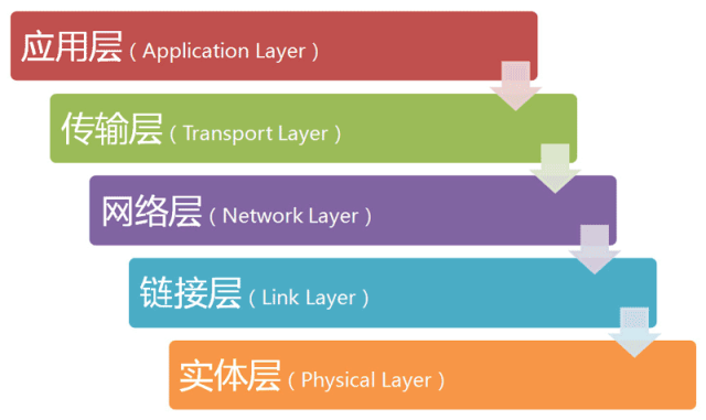
As shown in the image above, the bottom layer is called the “Physical Layer”, and the top layer is called the “Application Layer”. The three middle layers (from bottom to top) are the “Link Layer”, “Network Layer”, and “Transport Layer”. The lower the layer, the closer it is to the hardware; the higher the layer, the closer it is to the user.
The names of these layers are not particularly important. It’s enough to know that the internet is divided into several layers.
1.2 Layers and Protocols
Each layer is designed to accomplish a specific function. To achieve these functions, everyone must adhere to common rules.
These commonly adhered-to rules are called “protocols”.
Each layer of the internet defines many protocols. The collective name for these protocols is the “Internet Protocol Suite”. They are the core of the internet, and the following sections introduce the functions of each layer, primarily focusing on the main protocols of each layer.
02 Physical Layer
Let’s start from the bottom layer.
When computers are to be networked, what is the first thing to do? Of course, it’s to connect the computers using optical fibers, cables, twisted pairs, or radio waves.
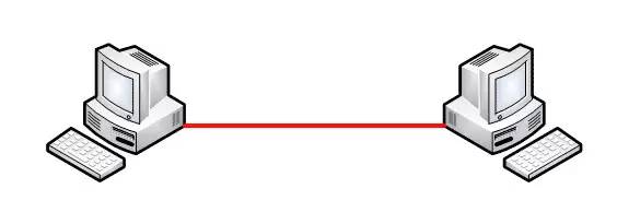
This is called the “Physical Layer”; it is the physical means of connecting computers. It mainly specifies some electrical characteristics of the network and is responsible for transmitting electrical signals of 0s and 1s.
03 Link Layer
3.1 Definition
Raw 0s and 1s have no meaning; a method of interpretation must be established: how many electrical signals constitute a group? What does each signal bit signify? This is the function of the “Link Layer”, which sits above the “Physical Layer” and determines how 0s and 1s are grouped.
3.2 Ethernet Protocol
In the early days, each company had its own method of grouping electrical signals. Gradually, a protocol called “Ethernet” became dominant.
Ethernet specifies that a group of electrical signals forms a data packet called a “Frame”. Each frame is divided into two parts: the header (Head) and the data (Data).

The “header” contains some descriptions of the data packet, such as sender, receiver, data type, etc.; the “data” is the specific content of the data packet.
The length of the “header” is fixed at 18 bytes. The length of the “data” is at least 46 bytes and at most 1500 bytes. Therefore, the entire “frame” is at least 64 bytes and at most 1518 bytes. If the data is long, it must be split into multiple frames for transmission.
3.3 MAC Address
As mentioned above, the “header” of the Ethernet data packet contains information about the sender and receiver. So how are the sender and receiver identified?
Ethernet requires that all devices connected to the network must have a “network card” interface. Data packets must be transmitted from one network card to another. The address of the network card is the sending and receiving address of the data packet, known as the MAC address.
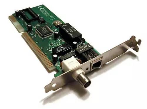
Each network card has a unique MAC address, consisting of 48 bits, usually represented by 12 hexadecimal numbers.
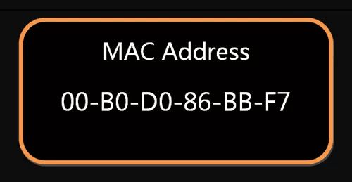
The first 6 hexadecimal numbers are the vendor ID, and the last 6 are the serial number of the network card from that vendor. With the MAC address, the path of the network card and data packet can be identified.
3.4 Broadcasting
Defining the address is just the first step; there are more steps to follow.
First, how does one network card know the MAC address of another network card?
The answer is that there is an ARP protocol that can solve this problem. This will be introduced later; here it is only necessary to know that Ethernet data packets must know the MAC address of the recipient before they can be sent.
Secondly, even if the MAC address is known, how can the system accurately deliver the data packet to the recipient?
The answer is that Ethernet uses a very “primitive” method; it does not send the data packet directly to the recipient but broadcasts it to all computers in the network, allowing each computer to determine whether it is the recipient.
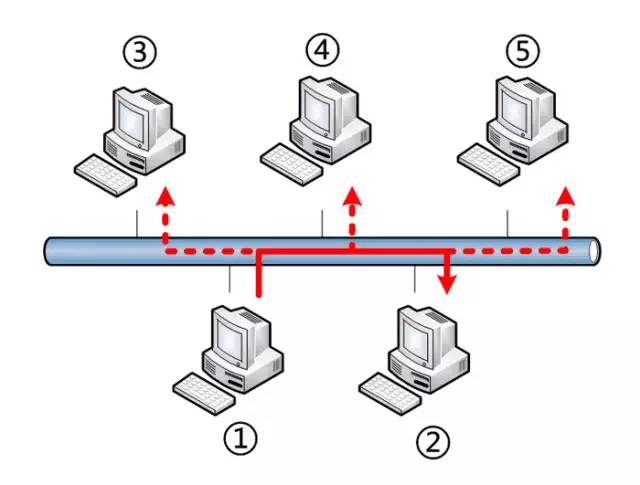
In the image, computer 1 sends a data packet to computer 2; computers 3, 4, and 5 in the same subnet will also receive this packet. They read the “header” of the packet, find the recipient’s MAC address, and compare it with their own MAC address. If they match, they accept the packet for further processing; otherwise, they discard it. This sending method is called “broadcasting”.
With the definition of data packets, the MAC address of network cards, and the broadcasting method, the “Link Layer” can transmit data between multiple computers.
04 Network Layer
4.1 Origin of the Network Layer
Ethernet protocol relies on MAC addresses to send data. In theory, a MAC address in Shanghai can find a MAC address in Los Angeles; technically, it is feasible.
However, this method has a significant drawback. Ethernet uses broadcasting to send data packets; all members receive a “packet”, which is inefficient and limited to the subnet of the sender. In other words, if two computers are not in the same subnet, broadcasting cannot reach them. This design is rational; otherwise, every computer on the internet would receive all packets, which would lead to disaster.
The internet is a giant network composed of countless subnets; imagining that a computer in Shanghai and a computer in Los Angeles would be in the same subnet is nearly impossible.
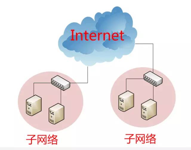
Therefore, a method must be found to distinguish which MAC addresses belong to the same subnet and which do not. If they are in the same subnet, broadcasting can be used; otherwise, routing must be used. (“Routing” refers to how to distribute data packets to different subnets, which is a vast topic and will not be covered in this article.) Unfortunately, MAC addresses cannot accomplish this; they are only related to the vendor and not to the network they are in.
This led to the birth of the “Network Layer”. Its function is to introduce a new address system that allows us to distinguish whether different computers belong to the same subnet. This address is called the “network address”, abbreviated as “URL”.
Thus, after the emergence of the “Network Layer”, each computer has two addresses: one is the MAC address, and the other is the network address. The two addresses are not related; the MAC address is bound to the network card, while the network address is assigned by an administrator, and they are simply randomly combined.
The network address helps us determine the subnet of the computer, while the MAC address delivers the data packet to the target network card within that subnet. Therefore, logically, we must first process the network address and then the MAC address.
4.2 IP Protocol
The protocol that specifies the network address is called the IP protocol. The addresses it defines are known as IP addresses.
Currently, the widely used version is IP protocol version 4, abbreviated as IPv4. This version specifies that the network address consists of 32 bits.
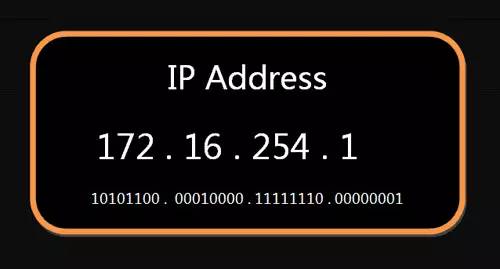
Traditionally, we represent an IP address as four segments of decimal numbers ranging from 0.0.0.0 to 255.255.255.255.
Each computer on the internet is assigned an IP address. This address is divided into two parts: the first part represents the network, and the second part represents the host. For example, the IP address 172.16.254.1 is a 32-bit address; assuming its network part is the first 24 bits (172.16.254), the host part is the last 8 bits (the last 1). Computers within the same subnet must have the same network part of their IP addresses, meaning 172.16.254.2 should be in the same subnet as 172.16.254.1.
However, the problem is that from the IP address alone, we cannot determine the network part. Taking 172.16.254.1 as an example, we cannot tell whether the network part is the first 24 bits, the first 16 bits, or even the first 28 bits, just from the IP address.
So how can we determine from the IP address whether two computers belong to the same subnet? This requires another parameter called the “subnet mask”.
The “subnet mask” is a parameter that indicates the characteristics of the subnet. It is formally equivalent to an IP address, also a 32-bit binary number, where its network part is all 1s and its host part is all 0s. For example, if the IP address is 172.16.254.1, and the known network part is the first 24 bits and the host part is the last 8 bits, then the subnet mask would be 11111111.11111111.11111111.00000000, which is written in decimal as 255.255.255.0.
Knowing the “subnet mask”, we can determine whether any two IP addresses are in the same subnet. The method is to perform an AND operation on the two IP addresses with the subnet mask (if both bits are 1, the result is 1; otherwise, it is 0) and then compare the results. If they are the same, it indicates that they are in the same subnet; otherwise, they are not.
For instance, if the IP addresses 172.16.254.1 and 172.16.254.233 both have a subnet mask of 255.255.255.0, we can check if they are in the same subnet. Performing the AND operation on both with the subnet mask yields 172.16.254.0, so they are in the same subnet.
To summarize, the IP protocol primarily serves two functions: one is to assign an IP address to each computer, and the other is to determine which addresses are in the same subnet.
4.3 IP Packet
The data sent according to the IP protocol is called an IP packet. It is easy to imagine that it must include IP address information.
However, as mentioned earlier, Ethernet data packets only contain MAC addresses and do not have a field for IP addresses. So do we need to modify the data definition to add a new field?
The answer is no; we can place the IP packet directly into the “data” portion of the Ethernet data packet, thus not requiring any modification to the Ethernet specifications. This is the benefit of the layered structure of the internet: changes in upper layers do not affect the structure of lower layers.
Specifically, the IP packet is also divided into “header” and “data” parts.
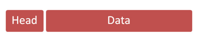
The “header” part mainly includes information such as version, length, and IP address, while the “data” part is the specific content of the IP packet. Once placed in the Ethernet data packet, the Ethernet data packet looks like this.
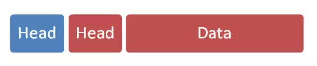
4.4 ARP Protocol
There is one last point to clarify regarding the “Network Layer”.
Since IP packets are sent within Ethernet packets, we must know both addresses: the MAC address of the other party and the IP address of the other party. Typically, the IP address of the other party is known (to be explained later), but we do not know its MAC address.
Therefore, we need a mechanism to obtain the MAC address from the IP address.
This can be divided into two situations. The first situation is when the two hosts are not in the same subnet; in this case, it is impossible to obtain the MAC address of the other party, and we can only send the data packet to the “gateway” connecting the two subnets and let the gateway handle it.
The second situation is when the two hosts are in the same subnet; in this case, we can use the ARP protocol to obtain the MAC address of the other party. The ARP protocol also sends a data packet (contained within an Ethernet packet) that includes the IP address of the host to be queried, with the MAC address field filled with FF:FF:FF:FF:FF:FF, indicating this is a “broadcast” address. Every host in the subnet will receive this data packet, extract the IP address, and compare it with its own IP address. If they match, they will respond by reporting their MAC address; otherwise, they discard the packet.
In summary, with the ARP protocol, we can obtain the MAC addresses of hosts within the same subnet and send data packets to any host.
05 Transport Layer
5.1 Origin of the Transport Layer
With MAC and IP addresses, we can establish communication between any two hosts on the internet.
The next issue is that many programs on the same host need to use the network. For example, while browsing the web, you may also be chatting online. When a data packet arrives from the internet, how do you know whether it represents web content or online chat content?
This means we need another parameter that indicates which program (process) the data packet is intended for. This parameter is called a “port”; it is essentially a number assigned to each program using the network card. Each data packet is sent to a specific port on the host, allowing different programs to access the data they need.
The “port” is an integer between 0 and 65535, exactly 16 bits. Ports from 0 to 1023 are reserved for the system, and users can only use ports greater than 1023. Whether browsing the web or chatting online, applications will randomly select a port and connect with the corresponding server port.
The function of the “Transport Layer” is to establish communication from “port to port”. In contrast, the function of the “Network Layer” is to establish communication from “host to host”. Once the host and port are determined, we can facilitate communication between programs. Thus, Unix systems refer to the combination of host and port as a “socket”. With this, network application development becomes possible.
5.2 UDP Protocol
Now, we must include port information in the data packet, which requires a new protocol. The simplest implementation is called the UDP protocol, which almost just adds the port number in front of the data.
UDP packets also consist of “header” and “data” parts.
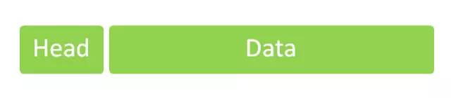
The “header” part mainly defines the sending and receiving ports, while the “data” part contains the specific content. Then, the entire UDP packet is placed in the “data” part of the IP packet. As mentioned earlier, the IP packet is also contained within the Ethernet packet, so the entire Ethernet packet now looks like this:

The UDP packet is very simple; the “header” part is only 8 bytes, and the total length does not exceed 65,535 bytes, perfectly fitting into an IP packet.
5.3 TCP Protocol
The advantage of the UDP protocol is its simplicity and ease of implementation, but its drawback is poor reliability; once a data packet is sent, it cannot be confirmed whether the other party has received it.
To address this issue and improve network reliability, the TCP protocol was created. This protocol is quite complex but can be roughly seen as a UDP protocol with an acknowledgment mechanism; every time a data packet is sent, an acknowledgment is required. If a data packet is lost, the sender knows it needs to resend that packet.
Therefore, the TCP protocol ensures that data is not lost. Its downside is that the process is complex, difficult to implement, and consumes more resources.
TCP packets, like UDP packets, are embedded in the “data” part of the IP packet. TCP packets have no length limit; theoretically, they can be infinitely long. However, to ensure network efficiency, the length of TCP packets typically does not exceed that of IP packets, ensuring that a single TCP packet does not need to be split.
06 Application Layer
Once the application program receives data from the “Transport Layer”, it must interpret it. Since the internet has an open architecture and data comes from various sources, a format must be predetermined; otherwise, it cannot be interpreted.
The function of the “Application Layer” is to specify the data formats for applications.
For example, the TCP protocol can transmit data for various programs, such as Email, WWW, FTP, etc. Therefore, different protocols must define the formats of email, web, and FTP data; these application protocols constitute the “Application Layer”.
This is the highest layer, directly facing the user. Its data is placed in the “data” part of the TCP packet. Thus, the Ethernet data packet now looks like this.
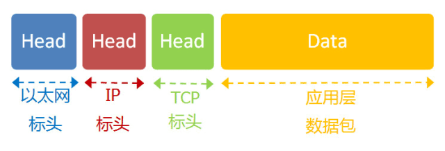
Thus, the entire five-layer structure of the internet has been explained from the bottom up. This is an explanation of how the internet is constructed from a systems perspective.
10T Technical Resources Giveaway! Including but not limited to: Cloud Computing, Virtualization, Microservices, Big Data, Networking, Docker Containers, Kubernetes, Linux, Python, Go, C/C++, Shell, etc. Reply “1024” in the public account to get it for free!!
▼If you like it, give me a“Like”