
 :Click↑“Power Supply Alliance” to subscribe to the first self-media of the high-reliability power supply industry
Power Supply Alliance—The first self-media of the high-reliability power supply industry
Here you can find power supply technology dry goods, analysis of power supply industry development trends, introduction of the latest power supply products, and many power supply experts sharing their technical experience. Follow us and grow with the Chinese power supply industry!
Power Supply Design for Ship Integrated Control System Based on Modular Power Supply
Introduction
A certain ship’s integrated control system uses an embedded single-board computer with a VME bus from SBS company as the central control console’s main computer, requiring a stable voltage supply, high conversion efficiency, low ripple and noise, and good heat dissipation, while also needing a compact structure for installation in a standard 6U high chassis.
This power supply design can adopt two methods: either design from the most basic power conversion unit to a complete functional prototype, or optimize and integrate based on mature power conversion functional modules with auxiliary circuits (output voltage regulation, voltage detection alarm, etc.) to create a suitable, efficient, and reliable power module. Considering that well-known companies in the domestic and international power supply field have developed a complete range of modular power supplies based on market demand, adopting the second method can complete the power supply system design and development more flexibly and quickly, shortening the development cycle and saving manpower and design costs. At the same time, using modular power supplies can significantly reduce external wiring, solder points, or connection points, thus greatly increasing product reliability.
Currently, well-known brands of modular power supplies at home and abroad include Vieor from the USA, Cosel from Japan, and LAMBDA, among which the Vicor series modules have obvious advantages in power density, heat management, and configuration flexibility, widely used in harsh environments and high reliability requirements, making them the preferred power supply for computers in harsh environments. This article designs the power supply for a certain embedded single-board computer using Vicor modules based on actual project requirements.
1 Power Supply Design and Implementation
1.1 Basic Requirements and Technical Solutions
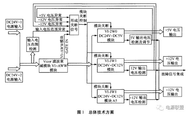
According to the system’s power supply planning, the power supply module to be designed can obtain two channels of DC24V input power. Therefore, the basic requirement of this power supply design is to convert the DC24V power supply into DC+5V and ±12V working power supply that meets the requirements of the single-board computer. Based on the design requirements and the specifications of the Vicor series modules, it is proposed to use the VI-IAM module (Input Attenuator Module) to filter the input power supply first, and then use the VI-2W0 and VI-JW1 modules to further convert it into DC+5V and ±12V. The overall technical scheme is shown in Figure 1.
1.2 Dual Redundant Input Design, Input Power Status Monitoring, and Filtering
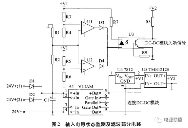
To improve system reliability, dual redundant power supply is adopted, and the dual power input and input voltage upper and lower limit monitoring and filtering circuit are shown in Figure 2. In the figure, two channels of DC24V input power are supplied redundantly through two diodes. To meet EMC technical requirements and reduce noise interference, the VI-IAM module A1 is used for filtering. The VI-IAM input attenuator module is a DC input front-end filter that can ensure EMC technical performance requirements when used with Vicor converter modules. To detect the input voltage range, a voltage upper and lower limit comparison circuit centered on an operational amplifier is set up. When the input voltage exceeds the set upper or lower limit threshold, an abnormal input voltage signal is generated through an optocoupler to shut down the lower DC/DC module. The reference voltage for the input of the operational amplifier used as a comparator is provided by the output of the 7812 voltage regulator, while the output of the DC/DC converter TME1212S is used as the working power supply for the optocoupler output circuit.
1.3 DC/DC Conversion Main Circuit and Regulation Circuit Design
The DC/DC conversion main circuit and regulation circuit are shown in Figure 3. The DC24V input voltage is filtered by the VI-IAM input attenuator module and then converted into +5V and ±12V DC voltage through the VI-2W0 and VI-JW1 modules. To ensure that the output voltage of the DC/DC converter has a certain adjustable range or remains stable at the nominal value when the input voltage deviates from a certain range or when the load effect is significant, an external voltage adjustment resistor network is connected at the output of the VI-2W0 and VI-JW1 modules according to the design and calculation methods recommended in the Vicor module application manual. Taking the adjustment of the +5V output voltage of the VI-2W0 module as an example, a potentiometer R4 with a resistance value of 10 kΩ is used to adjust the output voltage, while resistors R2 and R3 are used to limit the range of voltage lowering and raising. When R2 is selected as 23.63kΩ and R3 as 90KΩ, the output voltage can be adjusted within ±10%. The circuit in the dashed box in Figure 3 is used to smooth the fluctuations of the input voltage of the DC/DC converter. When there are significant instantaneous disturbances in the input voltage, two large-capacity electrolytic capacitors C13 and C14 will smooth the input voltage fluctuations through charging and discharging, ensuring the normal operation of the DC/DC converter.
1.4 DC/DC Conversion Module Shutdown Protection Function Circuit Design
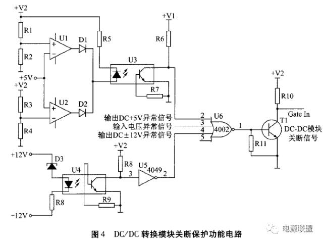
When the input voltage and output voltage of the DC/DC conversion module deviate significantly, in order to ensure the reliable operation of the embedded single-board computer system and interface boards, the power supply circuit should set a self-shutdown protection function: that is, automatically shut down the power supply module when there is an abnormal input or output, protecting the load circuit. The DC/DC conversion module shutdown protection function circuit designed in this article is shown in Figure 4.
Since DC+5V is the most important power supply for the embedded single-board computer, it should have higher power quality and better stability. The voltage upper and lower limit comparator circuit in Figure 4 detects the output voltage of DC+5V, and when the voltage deviates significantly from the normal value, an output voltage abnormal signal is generated through an optocoupler. DC±12V is the power supply for the fans and other interface components in the computer, and the power quality requirement can be lower than that of DC+5V. To simplify the circuit design, a voltage regulator D3 and optocoupler U4 are used to form the voltage status detection circuit for the DC±12V output voltage. When there is an abnormal input or output voltage, the shutdown signal generated by the relevant detection circuit serves as an input to the NOR gate 4002, outputting a total shutdown signal. When transistor T1 is turned on, the level of the Gate In pin connected to it is pulled low, shutting down the DC/DC converter.
1.5 Other Issues
1.5.1 Heat Dissipation and Structural Design
Good heat dissipation design is very important for improving the reliable operation of the power supply. Poor heat dissipation can easily lead to degradation of power supply quality; practice shows that power supply functional failures are often caused by high-temperature thermal damage. Although Vicor power modules have high efficiency (80% to 90%), there is still 10% to 20% power loss, which dissipates in the form of heat. The power supply module designed in this article is installed in a standard 6U high chassis. If effective heat dissipation measures are not taken, this heat will raise the temperature of the power supply itself and the internal plug-in boards of the chassis, so the issue of power supply heat dissipation cannot be ignored. To properly address this issue, the power supply housing is designed in a form with good heat dissipation characteristics, with the heat dissipation surface of the Vicor power module mounted on the metal housing, and a fan configured at the bottom of the chassis to ventilate and dissipate heat from the power supply and other circuit boards, ensuring excellent heat dissipation characteristics.
1.5.2 Electromagnetic Compatibility Design
Good electromagnetic compatibility design of the power supply is an effective way to ensure that computers and other electronic devices are electromagnetically compatible and immune to interference. The corresponding measures have been taken in the circuit design discussed earlier, which are explained as follows:
1) The VI-IAM module is used in conjunction with the DC/DC converter to meet EMC technical performance requirements and reduce noise interference;
2) An X-type capacitor is connected at the input of the VI-IAM module (C1 in Figure 2), and Y-type bypass capacitors are connected between the input and output of the VI-2W0 and VI-JWl modules to the ground plane (C2, C3, C5, C6 in Figure 3) to reduce differential mode and common mode interference, meeting electromagnetic compatibility requirements;
3) The power supply uses a closed metal housing to ensure good electromagnetic shielding.
1 Power Supply Design and Implementation
The power supply designed and developed based on Vicor power modules is connected to the standard VME bus chassis according to the defined electrical characteristics and requirements, supplying power to the VME bus embedded single-board computer and other interface devices. After laboratory trial operation and long-term continuous assessment tests, it is shown that the power supply designed and developed based on Vicor modules fully meets all performance requirements. The methods proposed in this article for power supply design and implementation have unique advantages in terms of operational reliability, power density, conversion efficiency, load characteristics, electromagnetic compatibility, and heat dissipation characteristics.
Power Supply Alliance—The first self-media of the high-reliability power supply industry
Here you can find power supply technology dry goods, analysis of power supply industry development trends, introduction of the latest power supply products, and many power supply experts sharing their technical experience. Follow us and grow with the Chinese power supply industry!
Click“Follow” to learn about power supply knowledge with hundreds of thousands of engineers