As a type of industrial control computer, PLC has a structure similar to that of a regular computer; however, due to different usage scenarios and purposes, there are some structural differences.
Hardware Components of PLC
The basic structural block diagram of the PLC hardware system is shown in the figure.
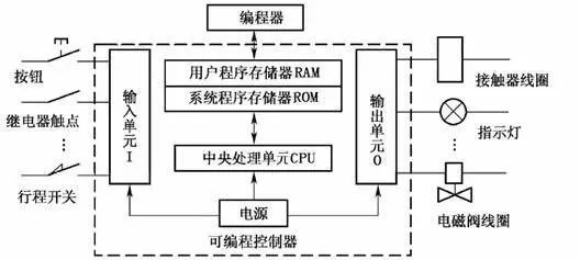
In the figure, the PLC host consists of a CPU, memory (EPROM, RAM), input/output units, peripheral I/O interfaces, communication interfaces, and power supply. For integrated PLCs, these components are all contained within the same casing.
For modular PLCs, each component is independently packaged, referred to as modules, which are connected together through racks and cables.
All parts inside the host are connected via power buses, control buses, address buses, and data buses, and external devices are equipped according to the actual control needs to form different PLC control systems.
Common external devices include programmers, printers, EPROM writers, etc. PLCs can be equipped with communication modules to communicate with the upper computer and other PLCs, forming a distributed control system.
The following sections will introduce the various components of the PLC and their functions to help users further understand the control principles and working processes of PLCs.
(1) CPU
The CPU is the control center of the PLC, coordinating the orderly operation of various devices in the field under its control. The CPU consists of a microprocessor and a controller, which can perform logical and mathematical operations, coordinating the work of the various parts of the control system.
The role of the controller is to ensure that all components of the microprocessor work in an orderly fashion. Its basic function is to read instructions from memory and execute them.
(2) Memory
The PLC is equipped with two types of memory: system memory and user memory. System memory is used to store the system management program, which the user cannot access or modify.
User memory is used to store the compiled application programs and working data states. The part of user memory that stores working data states is also called the data storage area, which includes the input/output data image area, timer/counter preset values and current data area, and a buffer for storing intermediate results.
The PLC memory mainly includes the following types.
(1) Read-Only Memory
(2) Programmable Read-Only Memory
(3) Erasable Programmable Read-Only Memory
(4) Electrically Erasable Programmable Read-Only Memory
(5) Random Access Memory
(3) Input/Output (I/O) Modules
① Digital Input Module
Digital input devices include various switches, buttons, sensors, etc. The input types of PLCs can typically be DC, AC, and AC/DC. The power supply for the input circuit can be provided externally, and some can also be provided internally by the PLC.
② Digital Output Module
The output module’s role is to convert the control signals output by the CPU, which are in TTL level, into signals needed to drive specific devices in the production field, thereby driving the action of the actuators.
(4) Programmer
The programmer is an important external device for the PLC. It can be used to send user programs into the PLC’s user program memory, debug programs, and monitor the execution process of programs. Programmers can be structurally divided into the following three types.
(1) Simple Programmer
(2) Graphic Programmer
(3) General Computer Programmer
(5) Power Supply
The power supply unit’s role is to convert external power (220V AC power) into internal working voltage. The externally connected power is converted into the working power needed by the PLC’s internal circuits (DC 5V, ±12V, 24V) through a dedicated switch-mode power supply equipped inside the PLC, and provides a 24V DC power supply for external input components (such as proximity switches) for input endpoints only. The power supply driving the PLC load is provided by the user.
(6) Peripheral Interfaces
The peripheral interface circuit is used to connect handheld programmers or other graphic programmers, text displays, and can form the PLC control network through peripheral interfaces. PLCs can connect to computers using PC/PPI cables or MPI cards through RS-485 interfaces, enabling programming, monitoring, networking, and other functions.
Software Components of PLC
The software of the PLC consists of system programs and user programs.
The system program is designed and written by the PLC manufacturer and stored in the PLC’s system memory, which users cannot directly read, write, or modify. The system program generally includes system diagnostic programs, input processing programs, compilation programs, information transfer programs, and monitoring programs.
The user program of the PLC is a program compiled by the user using the PLC’s programming language according to control requirements. In PLC applications, the most important aspect is to write user programs using the PLC’s programming language to achieve control objectives.
Since PLCs are specially developed devices for industrial control, their main users are electrical technicians. To meet their traditional habits and capabilities, the primary programming language of PLCs is a specialized language that is relatively simple, easy to understand, and visual compared to computer languages.
1. Graphical instruction structure
2. Clear variable constants
3. Simplified program structure 4. Simplified application software generation process
5. Enhanced debugging means
Basic Working Principle of PLC
The working mode of PLC scanning is mainly divided into three stages: input sampling stage, user program execution stage, and output refresh stage, as shown in the figure.
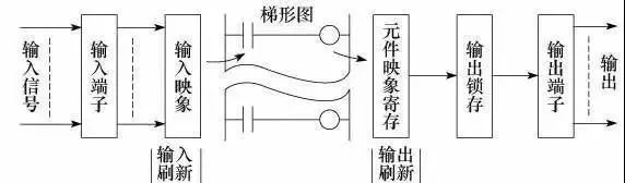
(1) Input Sampling Stage
During the input sampling stage, the PLC reads all input states and data sequentially in a scanning manner and stores them in the corresponding units in the I/O image area. After the input sampling is complete, it transitions to the user program execution and output refresh stages. In these two stages, even if the input states and data change, the states and data in the corresponding units of the I/O image area will not change.
Therefore, if the input is a pulse signal, the width of that pulse signal must be greater than one scanning cycle to ensure that the input can be read under any circumstances.
(2) User Program Execution Stage
In the user program execution stage, the PLC always scans the user program (ladder diagram) in a top-down order. When scanning each ladder diagram, it first scans the control circuit composed of various contacts on the left side of the ladder diagram, performing logical operations on the control circuit composed of contacts in the order of left to right and top to bottom; then, based on the results of the logical operations, it refreshes the status of the corresponding bit in the system RAM storage area or the corresponding bit in the I/O image area, or determines whether to execute the special function instructions specified by the ladder diagram.
During the execution of the user program, only the input points’ states and data in the I/O image area will not change, while the states and data of other output points and soft devices in the I/O image area or system RAM storage area may change, and the results of the program execution of the ladder diagram above will affect any ladder diagrams below that use these coils or data; conversely, the states or data of the refreshed logical coils of the ladder diagram below can only take effect on the ladder diagrams above during the next scanning cycle.
(3) Output Refresh Stage
Once the user program scanning is complete, the PLC enters the output refresh stage. During this time, the CPU refreshes all output latch circuits according to the corresponding states and data in the I/O image area, and then drives the corresponding peripherals through the output circuit. At this point, it is the true output of the PLC.
Input/Output Delay Phenomenon
From the working process of the PLC, the following conclusions can be drawn:
1. The program is executed in a scanning manner, and the logical relationship between the input/output signals has a theoretical delay. The longer the scanning cycle, the more serious the delay.
2. The scanning cycle includes not only the time occupied by the three main working stages: input sampling stage, user program execution stage, and output refresh stage, but also the time occupied by system management operations. Among them, the execution time of the program is related to the length of the program and the complexity of the instruction operations, while other factors remain basically unchanged. The scanning cycle is generally in the nanosecond range.
3. During the nth scanning execution of the program, the input data relied upon is the scanning value X from the sampling stage of that scanning cycle, while the output data has the previous scanning output value Y(n-1) and the current output value Yn; the signal sent to the output terminal is the final result Yn after executing all calculations this time.
4. Input/output response delay is related not only to the scanning method but also to program design arrangements.
Source: Internet, if there is any infringement, please leave a message to delete
Under the backdrop of Industry 4.0 and Intelligent Manufacturing 2025, “machine substitution” has become an inevitable trend, and industrial robots are hailed as the “crown jewel of the manufacturing industry.” Robot engineers are thus increasingly becoming a scarce high-paying profession. If you want to earn a high salary and enter a prestigious company, becoming a robot automation engineer is a great choice!


The certification for industrial robot maintenance personnel and operators is now completely free.
If you want to learn and obtain certification, please add the teacher’s WeChat.