As an embedded engineer, the following commonly used communication protocols are often essential knowledge in interviews.
1. UART Protocol
UART (Universal Asynchronous Receiver/Transmitter) is a bidirectional, serial, asynchronous communication bus that can achieve full-duplex communication with just one data receiving line and one data sending line.
Typical serial communication uses three lines: the transmit line (TX), the receive line (RX), and the ground line (GND). For communication to work properly, the TX and RX of both parties must be cross-connected, and GND must be connected.
-
Protocol Characteristics
-
Asynchronous:
-
No shared clock signal line is required.
-
Serial:
-
Single data line for serial transmission.
-
Full Duplex:
-
TX (Transmit): The data sending line (output from the perspective of this device).
-
RX (Receive): The data receiving line (input from the perspective of this device).
-
Point-to-Point:
-
The standard UART protocol is designed to connect two devices.
-
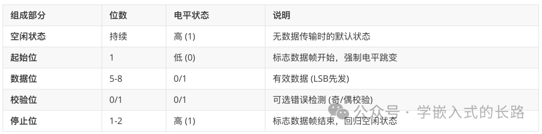
Data Frame Format
-
Start Bit:
-
1 bit of logic low (0), indicating the start of a new data frame.
-
Data Bits:
-
Typically 5, 6, 7, or 8 bits (most commonly 8 bits). These represent the actual data of one byte (or part of a byte) being transmitted.
-
The transmission order is usually least significant bit (LSB) first (i.e., bit0 is sent first, and bit7 is sent last).
-
Parity Bit:
-
Optional, can be 1 bit or none.Used for simple error detection (odd or even parity).
-
Odd Parity: The total number of “1” bits in the data bits + parity bit is odd.
-
Even Parity: The total number of “1” bits in the data bits + parity bit is even.
-
No Parity: The most common choice, which does not include a parity bit.
-
Stop Bits:
-
Typically 1 bit, 1.5 bits, or 2 bits (most commonly 1 bit).
-
Logic high (1), indicating the end of a data frame.
-
Provides separation between frames and ensures that the receiving circuit has enough time to reset and prepare to receive the next start bit.
-
Idle State:
-
When there is no data transmission, both TX and RX lines remain at logic high (1). The falling edge of the start bit pulls the line from idle high to low.

2. IIC Protocol
I²C Protocol (Inter-Integrated Circuit) is a synchronous, half-duplex, multi-master-slave architecture serial communication protocol developed by Philips (now NXP), designed for short-distance low-speed device communication on a board.
-
Protocol Characteristics
-
Signal Lines: SDA (Serial Data Line) + SCL (Serial Clock Line) (both are bidirectional open-drain outputs)
-
Topology: Bus type, multiple devices in parallel, addressed by address
-
Communication Mode: Half-duplex, can only send or receive at the same time
-
Speed Modes: Standard mode (100 kbps), Fast mode (400 kbps), High-speed mode (3.4 Mbps)
-
Addressing Capability: 7-bit address (supports up to 128 devices) or 10-bit address (supports up to 1024 devices)
-
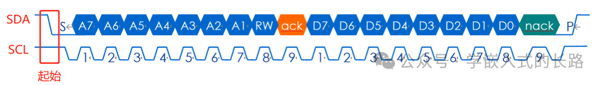
Data Frame Format
-
Start Condition (START)
-
When SCL is high, SDA transitions from high to low
-
Slave Address + Read/Write Bit (ADDRESS + R/W#)
-
7-bit Address: High 7 bits (MSB first)
-
Read/Write Bit::
<span>0</span>= Master writes,<span>1</span>= Master readsExample: EEPROM write operation at address<span>0x50</span>→<span>1010000 0</span>(binary)
-
Acknowledge Bit (ACK/NACK)
-
ACK: In the 9th clock cycle, the receiver pulls SDA low
-
NACK: SDA remains high (indicating an error or end of transmission)
-
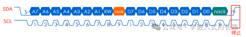
Data Byte (DATA)
-
Each byte is 8 bits (MSB first), followed by ACK/NACK
-
Acknowledge Bit (ACK/NACK)
-
ACK: In the 9th clock cycle, the receiver pulls SDA low
-
NACK: SDA remains high (indicating an error or end of transmission)
-
Stop Condition (STOP)
-
When SCL is high, SDA transitions from low to high
-
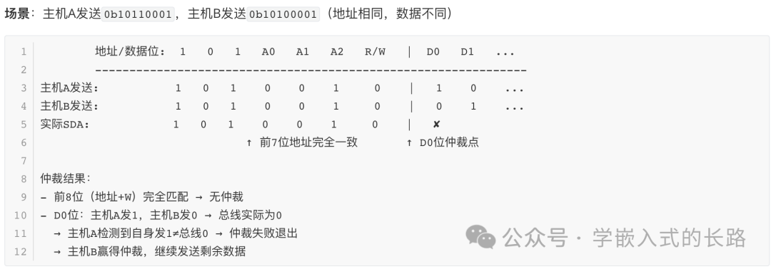
Data Arbitration
-
Clock Synchronization
-
Line and Logic: The SCL line is controlled in parallel by all masters; any device pulling SCL low causes the bus to go low
-
Longest Low Level Wins: The master with the longest low level duration determines the low phase period of SCL
-
Data Arbitration
-
Each master samples the SDA state during the SCL high level
-
If the level sent by itself does not equal the actual level on the bus, it immediately exits the competition
-
Failure Behavior
-
Switch to slave mode, listen to the communication of the master that won the arbitration
-
Release control of SCL
-
Cache unsent data, wait for the bus to be idle before retrying
-
End of Arbitration
-
When a master successfully sends data without interruption, it becomes the bus controller
-
Releases the bus after sending the STOP condition
3. SPI Protocol
SPI Protocol (Serial Peripheral Interface) is a high-speed, full-duplex, synchronous serial communication protocol developed by Motorola, designed for short-distance communication between chips on a board.
-
Protocol Characteristics
-
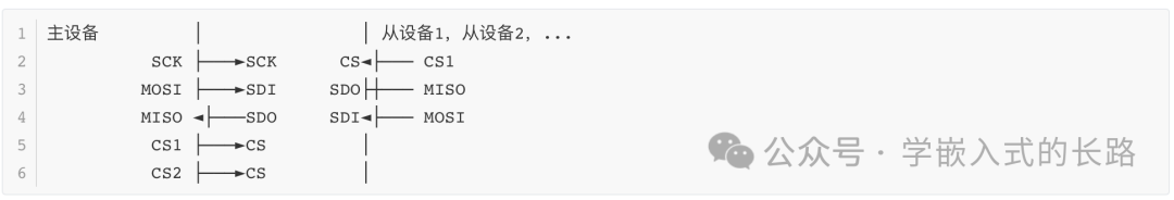
Signal Lines: CS (Chip Select), SCK (Clock Line), MOSI (Master Out Slave In Data Line), MISO (Master In Slave Out Data Line)
-
Topology: Master-slave architecture (one master, multiple slaves), addressed by chip select signals
-
Communication Mode: Full duplex
-
Transmission Speed: Typically 10-100 Mbps
-
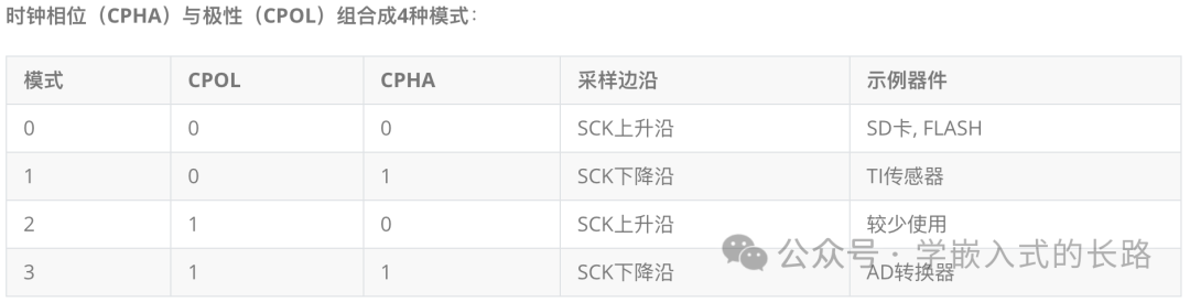
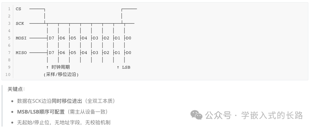
Data Transmission Timing
-
Data Frame Format
-
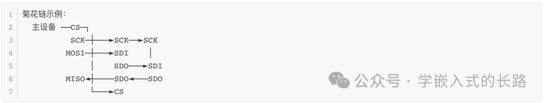
Multi-Slave Mode
-
Independent CS: No interference, optimal speed, but requires more IO ports
-
Daisy Chain: Only one CS is needed, data is stacked, speed is limited