Source | Pistachio Need Car
Knowledge Circle | Join the in-vehicle camera community, add WeChat 13501975564, note “Vision”
In engineering, issues related to sleep and wake-up are numerous, and many nodes in the vehicle’s network topology face similar problems. For example: communication loss due to shared SPI, nodes unable to sleep, node startup times exceeding requirements, and nodes occasionally failing to wake up, etc. These engineering issues are often attributed to network management, communication, or power management problems… It seems that these issues have become a mystery, and engineers from various modules are reluctant to get too involved. I cannot say that the above viewpoints are wrong; indeed, these problems involve power management, communication, network management, etc., and require engineers to have a certain understanding of the circuit principles, network management, and communication (especially the driver part) of the company’s products to properly recognize the issues and find suitable solutions.
This article attempts to discuss the power-up and power-down of MCUs from the perspective of circuit principles.
1. Conditions for MCU Power-Up
Regarding the wake-up conditions of uC (MCU), we have discussed this previously; you can refer to the earlier article “Embedded Development: How to Understand ECU Wake-Up, Sleep, and Reset?” The relationship between MCU power supply and the power management chip SBC (System Basic Chip) is illustrated as follows: Generally speaking, the wake-up of a node (MCU) is controlled by two aspects: hard lines and network disturbances.(1) Hard Line Wake-Up of MCUThe so-called hard line can be understood as IO operations, for example: KL15 hard line. The ignition we often refer to, from off to on, essentially corresponds to the closure action of the KL15 IO, which in turn enables the 12V power from the battery (KL30) to the ENA Pin of the SBC, after which the SBC outputs the operating voltage to the corresponding devices, e.g., Transceiver and uC.Note: The voltage output by the SBC to peripheral devices generally refers to the operating voltage required by these peripheral devices. In addition to the normal operating voltage, there are also some monitoring voltages, e.g., CAN Trcv is often connected to KL30 (Battery) for monitoring its own voltage and bus disturbances. As illustrated below, VBAT is a constant power (12V), while the Vcc (5V) and Vio (3.3V) used by Trcv are provided by the SBC. That is, in Sleep mode, if Trcv detects a wake-up event (Wakeup Pattern or specified network management message), it pulls up the INH Pin, thereby enabling the SBC to output the operating voltage to Trcv.
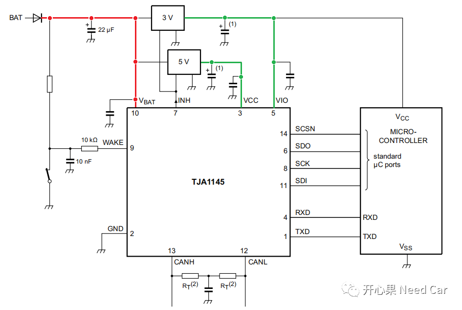 To simplify the scenario of hard line enabling the SBC, see the diagram below:
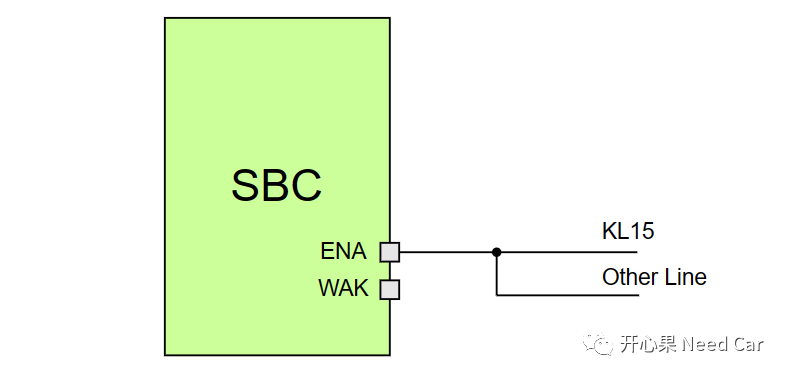 In the vehicle, some nodes are controlled by the KL15 hard line for wake-up, while others are not. If a node is controlled by KL15 hardware, the KL15 hard line generally acts on the SBC, which controls whether the uC is powered, thus enabling the possibility of node wake-up. In other words, different nodes have different numbers and methods of wake-up sources. Of course, some SBCs may be enabled not only by one KL15 hard line but also by other hard lines (Other Line). Regardless of how many external hard lines act on the SBC, generally speaking, these hard lines are in an OR relationship, meaning that each hard line can independently enable the SBC, thereby providing operating voltage to the MCU, Trcv, and other devices, thus waking up the corresponding devices.(2) Network DisturbanceThe so-called network disturbance essentially means meeting the wake-up timing of the Transceiver or receiving a specified network management message. In the vehicle, the number and types of buses used by various nodes may differ, which means that the enabling conditions for each node by the Bus are different. Generally, in the circuit design of a node, the INH Pin of the Trcv is connected to the WAK Pin of the SBC, as illustrated below:
 When the Trcv receives a specific wake-up timing or specified message, it pulls up the INH Pin, thereby pulling up the WAK Pin of the SBC, enabling the SBC, and subsequently, the SBC outputs operating voltage to the MCU, Trcv, and other devices, thus waking up the MCU.If a node uses multiple or several identical Trcvs, the INH of each Trcv and the SBC WAK are in parallel, meaning that any one of the Trcv’s INH can enable the SBC, thereby waking up the MCU.For the Lin bus, in engineering, it may not be used as a wake-up source but rather as a subordinate to the wake-up timing of CAN/Flexray/Ethernet.Note: The above only discusses waking up the MCU, and does not cover waking up the network; waking up the network requires checking the validity of the wake-up sources to avoid false wake-ups due to electromagnetic interference.
Conditions for MCU Power-Down
The power-down process (Shutdown) of the MCU is different from the power-up process; during power-up, as long as one wake-up source is triggered, the MCU can be awakened. However, for the MCU to power down, it must check each wake-up source, and only when all wake-up sources no longer request communication can the MCU execute the power-down process.What are the common checks for power-down in engineering? They are as follows:
- The status of all hard lines that trigger wake-up, i.e., whether KL15 and other hard lines are pulled low (Off state);
- Whether there are any diagnostic requests;
- Whether there are any network management messages;
- Whether there are any upper-layer user communication requests, etc.
When all of the above requests are not satisfied, the program begins to execute the MCU’s power-down process. In the Autosar architecture, the above conditions are periodically checked by BswM, and the rules in BswM need to be designed by the developer. Once the power-down process is satisfied, BswM will notify EcuM, which will control the power-down timing of the node.