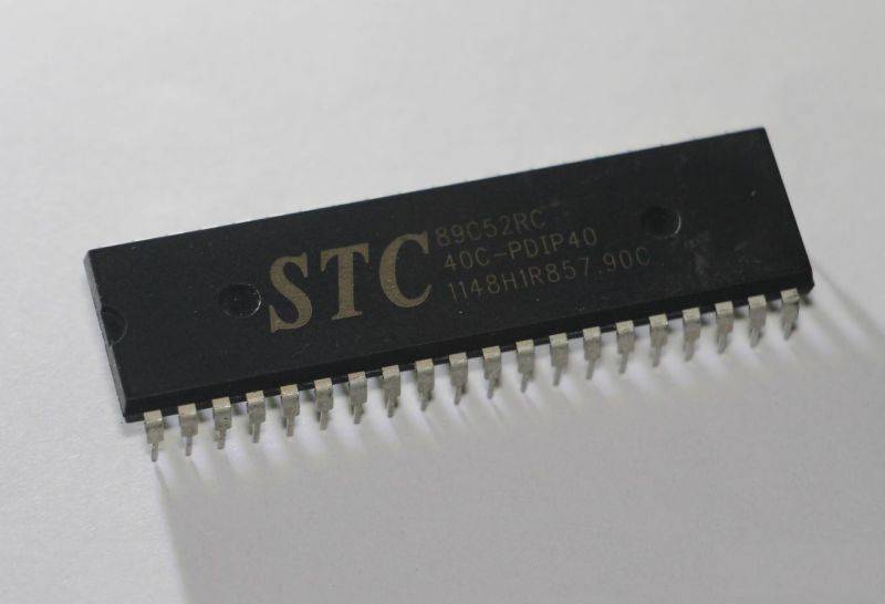
First, let us briefly introduce the specific functions of each pin of the 51 microcontroller, and then we will focus on the concept of the microcontroller minimal system, its composition, and the practical uses of the circuit diagrams of its various parts.
According to the pin identification method of integrated circuits, with the notch facing up and rotating counterclockwise, the pin numbers of the microcontroller range from 1 to 40, as shown in the figure. The names of each pin are also provided in the figure. There is no need to deliberately memorize the order and names of these pins; it is sufficient to look them up when needed. If used frequently, you will naturally remember them later.
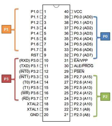
According to the hints in the large brackets in the figure, we refer to the eight pins P0.0~P0.7 as a group of IO ports, called P0, and similarly for P1, P2, and P3. IO ports (IO = Input / Output) are interfaces for input and output, serving as the means for the microcontroller to communicate with the outside world. Our main learning content will also revolve around IO ports. Additionally, these 32 IO ports have some pins with names indicated in parentheses, referred to as secondary functions; secondary functions will be enabled under specific conditions, and when not enabled, they only function as IO ports. For example, P3.0 and P3.1 are also called RXD and TXD, which serve serial port functions, allowing for program downloads to the microcontroller and data transmission and reception with a computer, i.e., serial communication. Aside from the 32 IO ports, there are eight additional pins: pins 29 to 31 are generally not used much and will not be introduced here; pin 40 (VCC), pin 20 (GND), pin 9 (RST), and pins 18 and 19 (XTAL1, XTAL2) will be explained in detail later in the minimal system of the microcontroller.
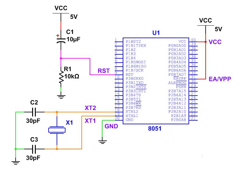
What is the microcontroller minimal system? The minimal system refers to the simplest circuit that allows the microcontroller to function properly. For the 51 microcontroller, the minimal system generally includes: power supply, microcontroller, clock circuit, and reset circuit. The circuit diagram is as follows:
Now, let’s introduce the functions of these circuits.
Power Circuit: As an electronic device, the 51 microcontroller certainly requires a power supply, typically using a 5V power supply, which can be obtained from the familiar USB interface. In the diagram, each VCC symbol is connected to the positive terminal of the 5V power supply; all GND symbols are connected together to the negative terminal of the power supply. The reason for not connecting them all together in the diagram, but using multiple VCC and GND symbols, is to make the circuit diagram clearer and more concise (VCC = Volt Current Condenser, indicating supply voltage; GND = Ground, meaning it can be simply understood as connected to the negative terminal of the power supply, with GND serving as the reference voltage, which is always 0V).
It is especially important to avoid connecting the microcontroller to a voltage that is too high or reversing the positive and negative terminals of the power supply, as this could potentially damage the microcontroller or even cause an explosion. If the microcontroller is inserted into a chip socket, due to the symmetrical positioning of VCC and GND, reversing them may lead to the power being connected incorrectly, so care must be taken to avoid this.
Additionally, if you need to know the power supply voltage used by a chip, you can usually refer to the official chip manual, which will be introduced later.
Clock Circuit: The circuit connected between pins XTAL1, XTAL2, and GND is the clock circuit (XTAL = External Crystal Oscillator). The power supply discussed earlier is quite understandable, but what is the clock circuit? What is its purpose? The clock circuit is like the heart of a person, constantly beating, and is crucial for the microcontroller. Just as the heart continuously transports blood and oxygen to our body, enabling various organs to function normally, the clock circuit serves as the driving force for the normal operation of the internal circuits of the microcontroller.
The clock circuit consists of a crystal oscillator and capacitors. The crystal oscillator is an electronic component made of quartz, which generates oscillations at a specific frequency when powered on, ultimately outputting a very stable clock signal through the circuit to drive the microcontroller. While our heart beats dozens to hundreds of times per minute, for the microcontroller, this is extremely slow. The frequency of the crystal oscillator in the diagram is 12MHz (1MHz = 1,000,000Hz), oscillating 12,000,000 times per second during normal operation! In fact, the clock circuit’s crystal oscillator does not have to be 12M; it can be other frequencies, but it is important to note that the maximum operating frequency of the STC89C51 microcontroller must not exceed 80M (this can also be found in the chip manual). In practice, we often use an 11.0592M crystal oscillator; the reason for this peculiar frequency will become clear when we discuss the serial port later.
The clock circuit also uses two capacitors, C2 and C3; if you’re unfamiliar with capacitors, you can look up relevant materials on commonly used electronic components, as we won’t cover that here. These two capacitors are usually ceramic capacitors, typically with a capacitance of 30pF.
Additionally, if you design a clock circuit yourself, the wiring between the crystal oscillator and the microcontroller should not be too long, as this could prevent the circuit from functioning properly (not oscillating).
The time taken for each oscillation of the clock is called a clock cycle; for the 51 microcontroller we are using, the microcontroller executes one operation every 12 clock cycles, referred to as a machine cycle (STC has also released 1T microcontrollers that execute one operation per clock cycle). If using a 12M crystal oscillator, the clock cycle is 1/12 us, and the machine cycle is exactly 1 us.
You may remember the ancient and massive ENIAC computer from the last century, which could perform 5000 addition operations per second, a remarkable achievement at the time. However, compared to our 51 microcontroller, it is quite insignificant. The 51 microcontroller can perform one addition operation (i.e., the assembly instruction ADD) in one machine cycle, and with a 12M crystal oscillator, it can perform up to one million addition operations per second, which is 200 times more than ENIAC (not considering data movement between registers and memory). At this point, aren’t you thrilled to be using such high-tech equipment? ^_^
Reset Circuit: The part of the circuit connected to the RST pin in the diagram is the reset circuit, consisting of a resistor and a capacitor. The function of the reset circuit is to send a signal to the microcontroller when power is first applied (for the 51 microcontroller, it is a high level for at least two machine cycles), informing the microcontroller that it can start working now. Consequently, the microcontroller begins executing a specific program from its initial state until power is cut off or a special condition causes the program to terminate. Generally, the microcontroller should not encounter a situation where program execution is terminated during normal operation; this will be discussed later when we cover the characteristics of microcontroller programs.
The principle of the reset circuit is to charge the capacitor through the resistor when powered on, allowing the voltage at the RST pin to drop from 5V to 0V, transitioning from high to low level. The values of the resistor and capacitor can be determined according to the reference values provided in the diagram; if you understand analog circuits, you can calculate their values yourself.
Moreover, the EA/VPP pin in the diagram is used for selecting access to internal or external program memory and providing programming voltage, which is generally not used much. It can be directly connected to VCC.
During actual experiments, I found that the microcontroller can often function without a reset circuit and without the two capacitors on the crystal oscillator; however, for safety reasons, it is advisable to include these components when possible. We should maintain a rigorous scientific attitude.
With the minimal system in place, the microcontroller can operate normally, continuously executing the programs we instruct it to perform. The microcontroller’s dedication and resilience are qualities we should learn from.