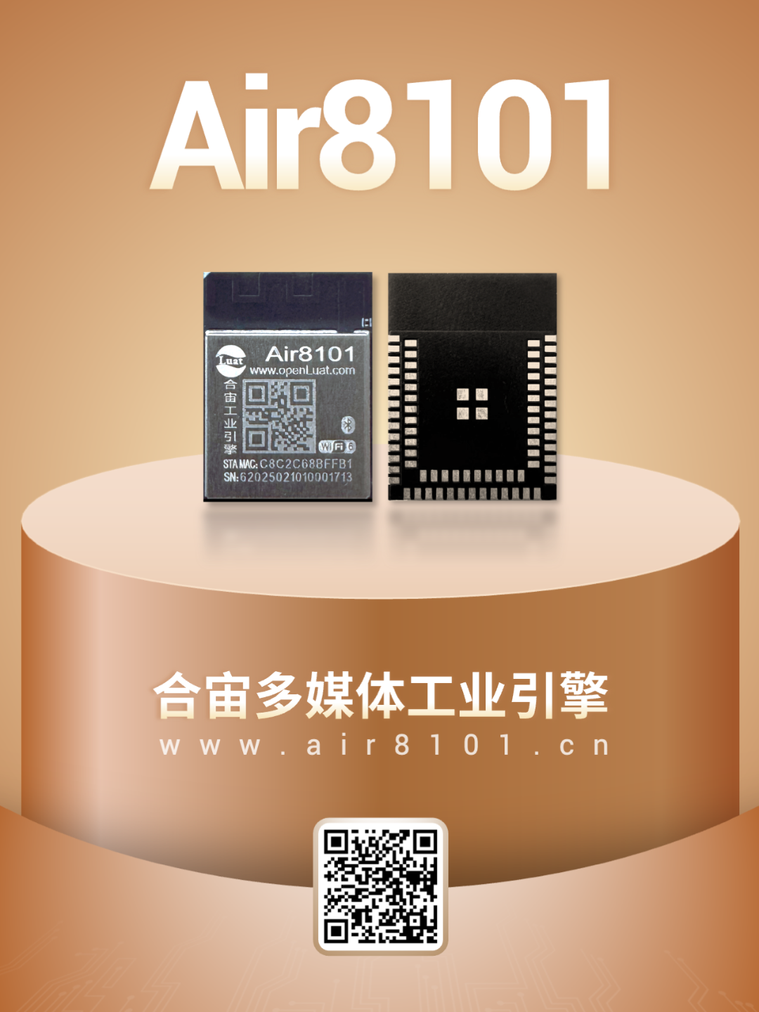
Hezong Air8101—— is a high-performance industrial engine that supports dual-mode 2.4GHz Wi-Fi 6 and Bluetooth (including classic Bluetooth and low-energy Bluetooth BLE 5.4), providing a rich set of functional interfaces including ADC, UART, I2C, SPI, QSPI, SDIO, Ethernet MAC, CAN, etc., and supports secondary development with LuatOS.
The ADC functionality of the Air8101 industrial engine provides critical analog signal acquisition capabilities for various IoT applications.
-
ADC typically refers to an Analog-to-Digital Converter, which is a device that converts continuous variable analog signals into discrete digital signals;
-
The ADC interface is mainly used to detect analog voltage signals for applications such as battery voltage detection, button detection, temperature and humidity detection, TDS detection, etc.
This article mainly shares some key considerations in the ADC design of the Air8101 industrial engine from a hardware design perspective, without delving deeply into software development.
1
External ADC of Air8101
1.1 Related Pins for External ADC
The Air8101 has 10 external ADCs, and the related pins are marked in the orange box in the figure below:
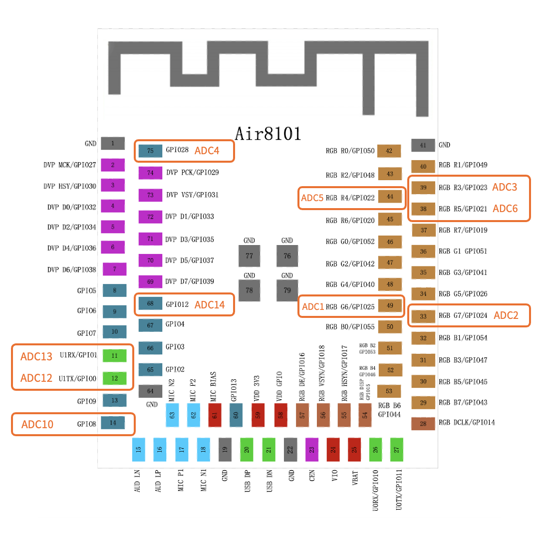
Note that these ADC pins have multiplexing functions:
-
In addition to being used as ADCs, they can also serve as GPIO, UART, PWM, I2C, SPI, RGB, and other functions.
-
During project design, if used for other multiplexed functions, they cannot be used as ADCs.
Download the Air8101 Pin Multiplexing Table:https://docs.openluat.com/air8101/product/shouce/
The Air8101 has ADC1, ADC2, ADC3, ADC4, ADC5, ADC6, ADC10, ADC12, ADC13, ADC14, totaling 10 external ADCs.
The corresponding relationships of these 10 ADCs are:
ADC1 corresponds to ADC10;
ADC2 corresponds to ADC12;
ADC3 corresponds to ADC13;
ADC4 corresponds to ADC14;
ADC5 and ADC6 do not correspond to any other ADC channels;
How should this correspondence be understood?
For example, ADC1 corresponding to ADC10 means that within the Air8101, ADC1 and ADC10 are the same ADC channel, and ADC1 and ADC10 cannot be used simultaneously.
1.2 Voltage Measurement Considerations
The external ADC of the Air8101 has a resolution of 12 bits; the voltage measurement range is from 0 to 2.4V, and internal voltage division is not supported.
1) When measuring external voltages not exceeding 2.4V:
If the voltage being measured from the external circuit does not exceed 2.4V, it can be directly connected to the ADC without any circuit processing;
2) When measuring external voltages exceeding 2.4V:
If the voltage on the north side of the external circuit exceeds 2.4V, the external voltage must be divided using resistors to ensure that the voltage applied to the ADC does not exceed 2.4V.
So, how should the voltage divider resistors be selected?
-
First, it depends on the value of the voltage being measured; the voltage divider resistors for measuring maximum voltages of 5V and 12V will definitely be different;
-
Secondly, the resistors must be of 1% precision to ensure that the voltage divider ratio meets the requirements as closely as possible;
-
Additionally, a filtering capacitor can be added at the ADC input to suppress high-frequency noise and avoid fluctuations in ADC readings.
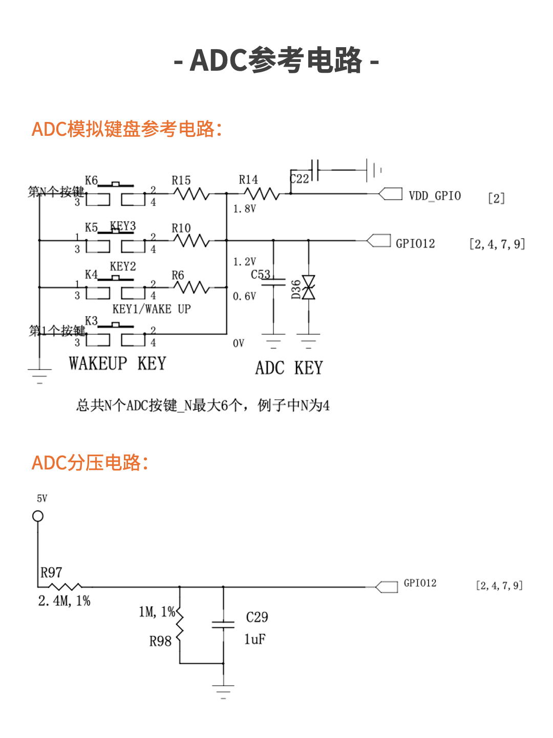
The above are all practical experiences. Now, let’s take an example where the external voltage being measured is 5V, and the voltage after division applied to the ADC is 1.5V:
▼ Voltage Divider Resistor Example ▼

Voltage Divider Ratio Requirement:
Vout/Vin=1.5V/5V=0.3,
i.e.: R2=0.3×(R1+R2),
Solving gives R1:R2≈2.33:1.
Recommended Resistor Values:
Pull-up resistor R1=2.4MΩ (±1% precision)
Pull-down resistor R2=1.0MΩ (±1% precision)
Actual Voltage Divider Ratio:
1.0MΩ/(2.4MΩ+1.0MΩ)≈0.294,
The voltage after dividing 5V is 5V×0.294≈1.47V, which meets the requirement of not exceeding 2.4V;
Correspondingly, if the voltage value measured by the ADC is 1.47V, it can be converted back to the measured voltage value as follows:
1.47V/0.294=5V;
It should be particularly noted that even when using MΩ-level resistors, the system will still have a fixed power consumption waste:
Total current: I=5V/(2.4MΩ+1.0MΩ)≈1.47μA
Total power consumption: P=5V×1.47μA=7.35μW
Power consumption is extremely low, suitable for low-power scenarios powered by batteries.
2
Internal ADC of Air8101
2.1 One ADC for detecting VBAT voltage
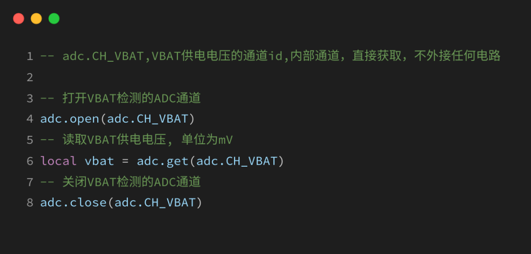
The Air8101 internally occupies one ADC for detecting the voltage of the VBAT pin:
-
No external hardware circuit is needed; the VBAT voltage can be read directly through the software API;
-
Voltage measurement range: 2.5V-4.35V;
You can use the following code to read the VBAT voltage:
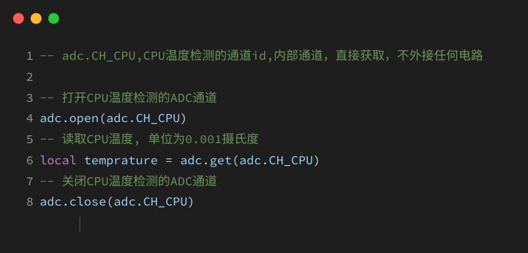
2.2 One ADC for detecting CPU temperature
The Air8101 internally occupies one ADC for detecting the CPU temperature:
-
No external hardware circuit is needed; it can be read directly through the software API;
-
Temperature measurement range: -40°C ~ +85°C;
You can use the following code to read the CPU temperature:
3
Hardware Design Reference
Hezong provides a complete hardware development reference design for the Air8101 (Ethernet, camera, audio amplifier, RS485, RS232, ADC, etc.), as well as an overall description of power design, which can be referenced in the link below for detailed information.
Download the latest hardware reference design materials for Air8101:
https://docs.openluat.com/air8101/luatos/hardware/design/reference/

That’s all for today’s content. You are welcome to join the technical exchange group or contact the person in charge for further discussion.

-
One to Four, USB Multi-Camera Data Acquisition and Processing
-
Two HMI Development Frameworks for Air8101: LVGL and AirUI
-
How to Design and Place Antennas? Three Common Layout Points
For more of the latest development materials, please refer to the Hezong Material Center:
—— docs.openluat.com