1. Introduction to EESkill NRF24L01 Wireless Module
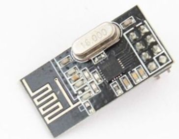
NRF24L01 is a wireless communication chip recently produced by NORDIC, using FSK modulation and integrating NORDIC’s own Enhanced ShortBurst protocol. It can achieve point-to-point or 1-to-6 wireless communication.The wireless communication speed can reach 2M (bps).NORDIC provides the GERBER files for the communication module, which can be directly processed for production.Embedded engineers or microcontroller enthusiasts only need to reserve 5 GPIOs and 1 interrupt input pin for the microcontroller system to easily achieve wireless communication, making it very suitable for building wireless communication functions for MCU systems.
1. 2.4G global open ISM frequency band, maximum 0dBm transmission power, license-free use.
2. Supports six-channel data reception, 2M bit/s makes high-quality VoIP possible.
3. Peak current of 12.5mA during reception at 2MBPS rate.
4. Peak current of 11mA at 2M bit/s output @ 0dBm.
5. Fast switching and wake-up time of 130μs.
6. Can operate at low voltage of 1.9 to 3.6V.
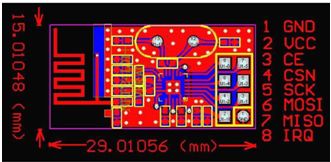
7. Size of 28mm * 15mm.
2. Wiring Instructions
Wiring instructions for using the NRF24L01 wireless module with the 51 microcontroller:
• IRQ —P1^5;
• MISO —P1^4;
• MOSI —P1^3;
• SCK —P1^2;
• CSN —P1^1;
• CE —P1^0;
• VCC — 3.3V
• GND — Ground
Wiring instructions for using the NRF2401 wireless module with Arduino:
IRQ — not connected;
• MISO —12;
• MOSI —11;
• SCK —13;
• CSN —7;
• CE —P1^0;
• VCC — 3.3V
• GND — Ground
3. Pin Description
4. Testing Instructions
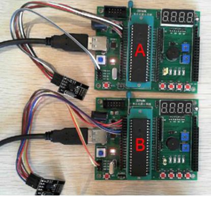
1. Testing with 51 development board and NRF2401 module
Main control chip:STC89C52RC
Hardware environment:Two Mini5V2.0 development boards + two NRF24L0 wireless modules
Testing program: CEPARKNRF24L0 wireless module test
Testing steps:
Using DuPont wires, connect 5 microcontroller pins P10, P11, P12, P13, P14, P15 to the NRF24L01 wireless module’s CE, CSN, SCK, MOSI, MISO, IRQ.
Connect the 3V3 and GND of the 51 microcontroller to the power input terminals VCC and GND of the NRF24L01 wireless module, using the minimum system of the 51 microcontroller to power the NRF24L0 wireless module.
Experimental phenomenon:
First, press the K1 button on board A, and the L1 light on board B turns on;Then, press the K2 button on board A, and the L1 light on board B turns off.And vice versa, achieving point-to-point transmission and reception with the wireless module.
2. Testing with Arduino development board and NRF2401 module
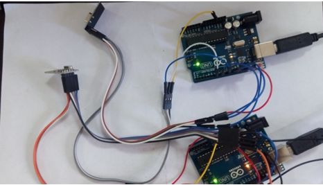
Hardware environment:Two Arduino modules + two NRF24L0 wireless modules
Testing steps:
Using DuPont wires, connect the digital pins 7, 8, 11, 12, 13 of the Arduino microcontroller to the CSN, CE, MOSI, MISO, SCK of the NRF24L0 wireless module.IRQ pin is not connected.
Connect the 3V3 and GND of the Arduino microcontroller to the power input terminals VCC and GND of the NRF24L0 wireless module.
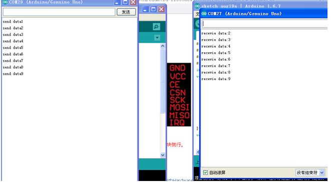
Write two programs into the microcontrollers, one as the transmitter and the other as the receiver, then open the serial port to get the following results:
The above content is for reference only!Relevant hardware purchase link is as follows:
cepark.taobao.com