The RF24L01+ operates in the 2.4~2.5GHz frequency band, features automatic retransmission, has 6 data transmission channels, and a maximum wireless transmission rate of 2Mbits. The MCU can access the chip’s registers for configuration via the SPI interface, enabling control of the module and the realization of wireless communication through this module.
For specific details, refer to <<Wildfire STM32–2.4G Wireless Transmission>>
Advantages: No connection establishment is needed for sending and receiving.
PCB Pinout
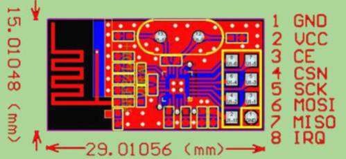
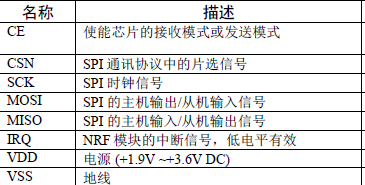
The functions of each interface are as follows:
In applications, we need a pair of transceivers, which means one master and one slave. The driver parts for the master and slave are the same (the configuration file SPI_NRF.c is identical), the difference lies in the mode called in the main function; the master usually operates in sending mode NRF_TX_Mode(); while the slave uses receiving mode NRF_RX_Mode();
Basic flow of the application
Notes:
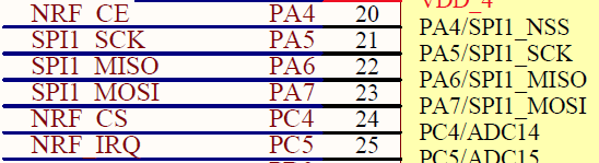
(1) First, check the wiring, generally configured as SPI1, and then connect according to the configuration in the program.
SPI1SCK = PA5 MISO = PA6 MOSI = PA7 CE = PA4 CSN = PC4 IRQ = PC5
The last two are used as general IO ports, any pins can be used.
Slave part:
(1) SPI_NRF_Init(); // Initialize SPI interface
(2) NRF_RX_Mode(); // Set to receiving mode
(3) Wait for reception in a while loop, check the reception status, and receive the data.
#include "stm32f10x.h"
#include "bsp_usart1.h"
#include "bsp_spi_nrf.h"
u8 status;         // For judging receive/send status
u8 rxbuf[4];     // Receive buffer
u8 i;

int main(void)
{
  /* Initialize UART1 */
  USART1_Config();
  /* Initialize SPI interface */
  SPI_NRF_Init();

  printf("\r\n This is an NRF24L01 wireless transmission experiment \r\n");
  printf("\r\n This is the feedback information from the wireless transmission slave end\r\n");
  printf("\r\n   Checking if NRF and MCU are connected properly...\r\n");  /* Check connection between NRF module and MCU */
  status = NRF_Check();
  if(status == SUCCESS)
    printf("\r\n      NRF and MCU connection successful\r\n");
  else
    printf("\r\n   Checking if NRF and MCU are connected properly...\r\n");

    NRF_RX_Mode();  // Set to receiving mode
    printf("\r\n Slave end enters receiving mode\r\n");  while(1)
  {
    /* Wait for data reception */
    status = NRF_Rx_Dat(rxbuf);    /* Check reception status */
    switch(status)
    {      case RX_DR:      for(i=0;i<4;i++)
      {
        printf("\r\n Slave end received data sent from master end: %d \r\n",rxbuf[i]);
      }break;
      case ERROR:
        printf("\r\n Slave end reception error.   \r\n");break;
    }
  }
}
Master part:
(1) SPI_NRF_Init(); // Initialize SPI interface
(2) NRF_TX_Mode(); // Set to sending mode
(3) Send data, check the sending status, otherwise resend. For example, use a button interrupt to send once.
Note: Usually a timeout is displayed, but the actual receiving end has received it.
Initialization and configuration are the same as the slave, except for TX mode.
Code for sending part:
void EXTI0_IRQHandler(void)
{    int i=0;    if(EXTI_GetITStatus(EXTI_Line0) != RESET)    // Ensure that an EXTI Line interrupt has occurred!!    {        for(i=0;i<4;i++)
        txbuf[i]+=1;
        printf("\r\n exit \r\n");
        status = NRF_Tx_Dat(txbuf);
      switch(status)
    {      case MAX_RT:
        printf("\r\n Master end did not receive the response signal, the number of transmissions exceeded the limit, sending failed. \r\n");      break;      case ERROR:
        printf("\r\n Sending failed due to unknown reasons. \r\n");      break;      case TX_DS:
        printf("\r\n Master end received the response signal from the slave end, sending successful! \r\n");
      break;
    }
}