
Click the blue text to follow us for basic knowledge and original content
SUBSCRIBE to US
1. Types of Antennas
With technological advancements, many manufacturers have launched various finished antennas to save research and development cycles. However, if engineers make poor choices, it not only fails to achieve the desired effect but also wastes a lot of time and costs on troubleshooting, which is not worth it. This article will introduce several commonly used antennas and provide design suggestions based on practical experience in engineering for reference.
Next, let’s introduce the common types of antennas:
(1) Onboard PCB Antenna: Made from PCB etching, it is cost-effective but has limited performance, good adjustability, and can be mass-produced for Bluetooth and WiFi wireless communication modules.
(2) SMT Patch Antenna: Commonly made of ceramic, it occupies less area, has high integration, is easy to replace, and is suitable for products with small space requirements. However, this type of antenna is slightly more expensive and has a narrower bandwidth.
(3) External Rod Antenna: Good performance, no need for debugging, easy to replace, high gain, suitable for various terminal devices.
(4) FPC Antenna: Connected via a feed line, it allows for flexible installation, high gain, and can usually be attached to non-metallic enclosures with adhesive, suitable for products with high performance requirements and sufficient enclosure space.
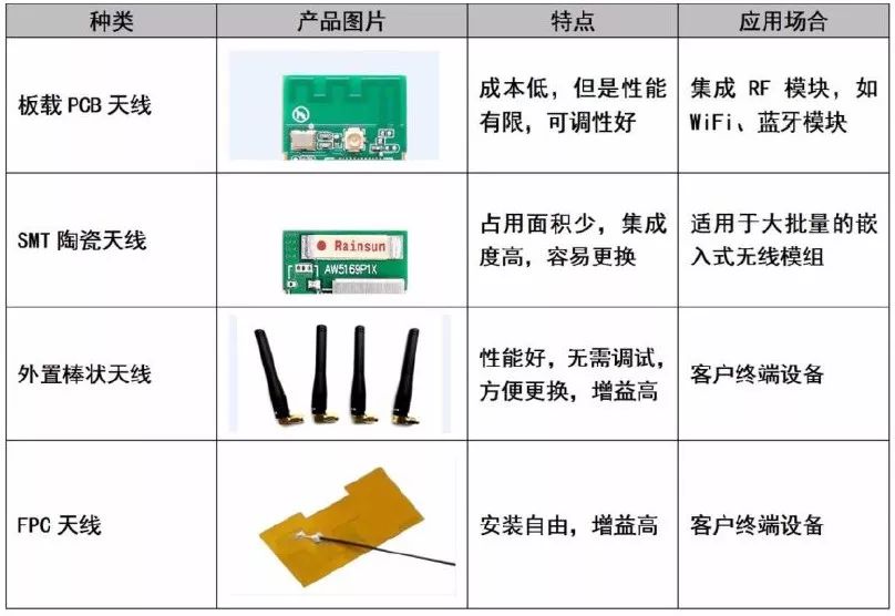
Figure 1 Common Antennas
The role of the antenna is to radiate RF signals into free space, and choosing the right antenna has a significant impact on transmission distance. Antennas are very sensitive to the surrounding environment, and in many cases, even if the right antenna is chosen, the expected effect may not be achieved. Since some customers are unclear about the factors to consider in antenna design, we provide some experience from actual engineering design to help customers better design their circuits and PCBs, thereby increasing the chances of project success.
2. Antenna Selection
The primary parameter affecting the communication distance of the wireless module is the transmission power. The transmission power of the wireless module and the corresponding ideal transmission distance can be found in the manual. After confirming that the transmission power meets the requirements, consider the selection of the antenna and its directionality.
First, the selection of the antenna:
The main indicators of the antenna include the following: frequency range, standing wave ratio (SWR or VSWR), antenna gain, polarization mode, and impedance. Choose the frequency range as needed; the standing wave ratio should preferably be less than 1.5; antenna gain also affects transmission distance; polarization can be linear or circular; impedance should match the output impedance of the wireless module, generally 50 ohms. Special attention should be paid to the standing wave ratio parameter; after purchasing the antenna, it is best to test the SWR with a network analyzer.
The table of standing wave ratio and return loss, transmission power is shown in Table 1.
Table 1 Standing Wave Ratio and Return Loss, Transmission Power
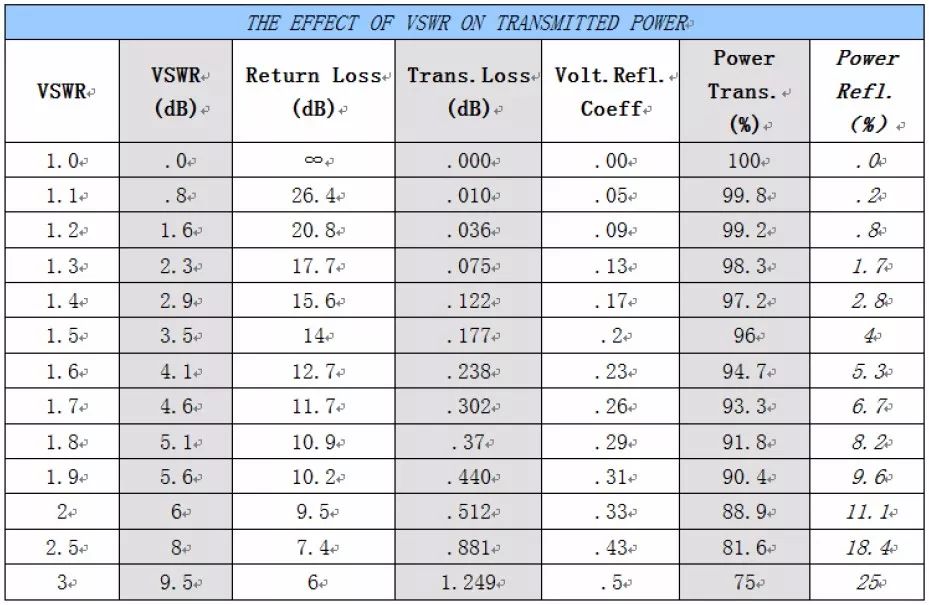
From the above table, it can be seen that when VSWR=1.5, the theoretical transmission power is 96%. When VSWR=2, the transmission power is only 88.9%. Some antennas have a standing wave ratio index of less than 2, so it is best to choose antennas with a standing wave ratio of less than 1.5 to achieve higher transmission power.
Secondly, the directionality of the antenna:
All antennas have directionality, which refers to the antenna’s ability to radiate or receive differently in different spatial directions. The directionality of the antenna is usually measured using a directional diagram, as shown in Figure 2, which is a directional diagram of an antenna with a frequency range from 2400MHz to 2500MHz.
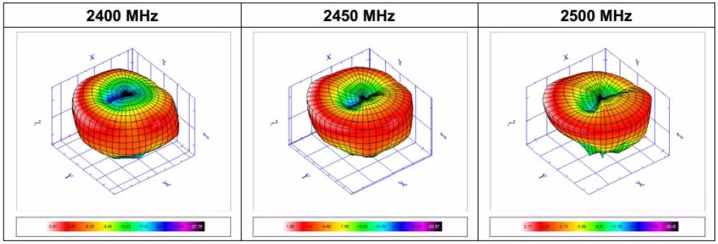
Figure 2 Three-Dimensional Directional Diagram of Antenna
When the antenna is placed vertically, the direction with the deepest red color indicates the strongest radiation or reception capability of the antenna. Therefore, when installing the antenna, it should be installed as much as possible in the direction indicated by the red color to ensure good signal quality. Additionally, metal plates can shield signals, so there should be no metal planes in the direction of transmission and reception.
Some antenna manuals provide directional diagrams in two-dimensional form, divided into H-Plane and E-Plane, as shown in Figure 3.
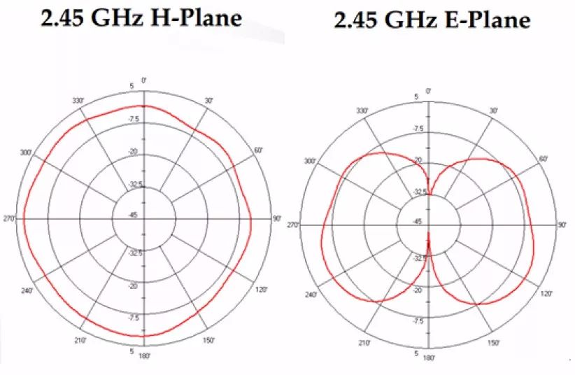
Figure 3 Two-Dimensional Directional Diagram of Antenna
When testing communication between wireless modules, the directionality of the antenna must be considered. When there are no obstructions in the communication space and the antenna direction corresponds to the strongest radiation direction, the communication distance can reach its maximum. If the antenna is improperly installed, it may lead to shorter communication distances or even no communication.
Engineers often encounter weak signals, communication distances not reaching the specifications in the manual, or high packet loss rates when testing wireless module communication. If the wireless module itself has no issues, it is advisable to first test the performance of the antenna itself, and then test according to the direction of strong signal radiation from the antenna for better testing results.
3. Antenna Circuit
1. Matching Circuit Design
In schematic design, it is necessary to reserve a π-type network between the antenna and the module’s RF output pin. The impedance of the antenna is affected by PCB ground, antenna installation, and surrounding metals. Reserving this network is to match it to 50 ohms when the antenna deviates significantly from 50 ohms.
X1, X2, X3 are reactive components. If the antenna has a standard 50-ohm impedance, then X2 and X3 can be left unconnected, and X1 should be connected to a 220PF capacitor or a 0-ohm resistor. In PCB design, these three components should be as close as possible to the module’s RF output pin, and the connecting transmission line should be short and straight. There should be no ground plane in the 1.5mm area around the matching components to reduce the impact of parasitic parameters on the matching circuit.
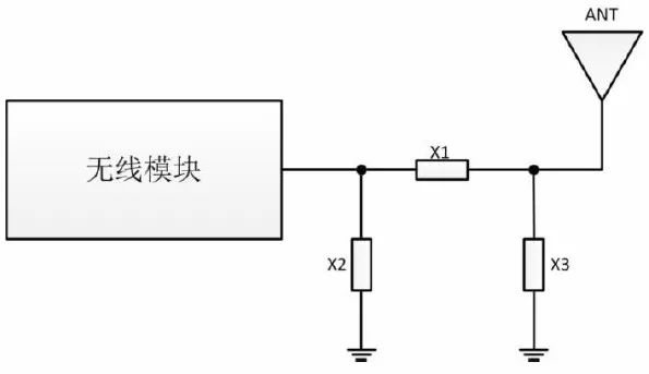
Figure 4 Matching Circuit
2. Microstrip Line Design
In PCB design, since most antennas and the module’s output impedance are 50 ohms, to minimize energy reflection during transmission, the PCB lead from the RF output pin to the antenna should be a 50-ohm microstrip line. The commonly used board material is FR4 (dielectric constant 4.2-4.6). Based on experience, when the line width is approximately 2.2 times the distance from the microstrip line to the reference layer, the characteristic impedance of the microstrip line is approximately 50 ohms. For specific designs, it is recommended to use microstrip line impedance control tools (ADS, txline, etc.) for calculations and complete the microstrip line design through actual debugging. As shown in the figure below, the ground layer under the microstrip line must be complete, and additional grounding vias should be added on both sides of the microstrip line.
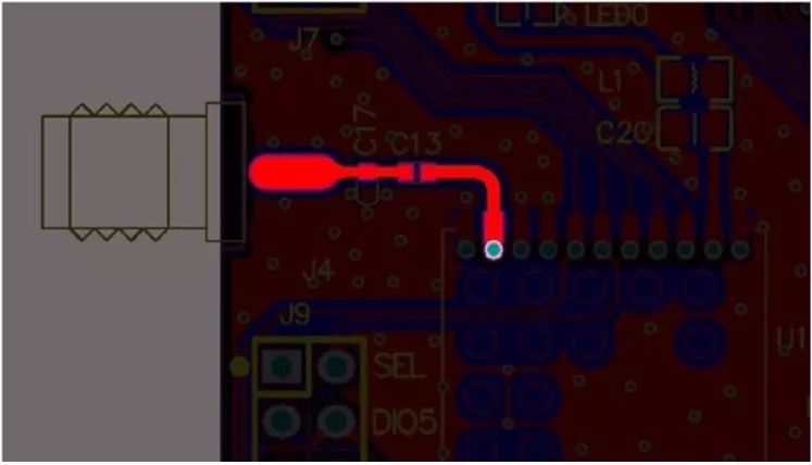
Figure 5 Microstrip Line
3. The Impact of Metal on Antennas
If there are metallic objects near the antenna, the metal can reflect electromagnetic waves, which not only affects the actual usage space of the antenna but also increases the loss resistance and reduces radiation efficiency, leading to degradation of the antenna’s radiation performance. When installing the antenna, pay attention to:
a: The antenna should be at least 5mm away from the battery;
b: The antenna should be at least 4mm away from the shielding case;
c: In cases where an enclosure needs to be installed, do not use paint or coatings with metallic components on the surface of the enclosure.
More Articles:
How to Start Antenna Design
Load Pull in Antenna Design
Design of Popular Wi-Fi Antennas
RF Q&A – Professional Microwave and RF Technology Community

Click “Read Original” to participate in interactive comments