As one of the most commonly used measuring instruments in the electronics industry, oscilloscopes involve a lot of image import/export, data processing, automation operations, and more. Here, we plan to explain in detail the remote control of oscilloscopes, with the following arrangements:
1 Remote image access and control via wireless network (suitable for special occasions or remote debugging)
2 Quick automation testing without a foundation based on special software (suitable for quick setup of simple automation tests)
3 Programming basics based on SCPI commands (what to pay attention to when learning programming?)
1. Remote Control of Oscilloscopes via Wireless Control
There are many situations where it is inconvenient to use a cable to connect a computer and an oscilloscope, such as when the desk is far from the test bench, when the laboratory needs to be fully enclosed for safety reasons, or when we want to check the oscilloscope waveform at home or anywhere else.
How to use wireless remote control for oscilloscopes
Monitor oscilloscope waveforms and control them in real-time from anywhere
The specific steps are as follows ↘↘↘
Step 1: Connect the oscilloscope to the router via an Ethernet cable, which can be used in a local area network (suitable for office environments) or a wide area network (for remote control anytime, anywhere).
Step 2: After successfully connecting the LAN port, check the oscilloscope’s IP address in the [Utility] system settings > I/O interface, for example: 130.29.70.57.
Step 3: Enter the oscilloscope’s IP address 130.29.70.57 in the address bar of the IE browser to automatically access the basic information interface of the oscilloscope:
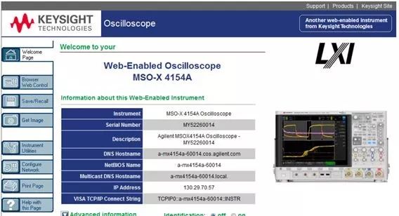
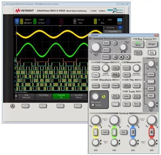
After installing the Java plugin as prompted by the system, you can access the full remote front panel of the oscilloscope under the Browser Web Control option, allowing you to control all functions of the oscilloscope, with the operation panel identical to the real panel of the oscilloscope.
You can also access the remote front panel with only the screen to control the oscilloscope from the oscilloscope menu.
Using the oscilloscope’s web interface allows you to:

o View information about the oscilloscope, such as model, serial number, hostname, IP address, and VISA (address) connection string.
o Control the oscilloscope using the remote front panel.
o Send SCPI (Standard Commands for Programmable Instruments) remote programming commands through the SCPI command mini-window view.
o Save settings, screen images, waveform data, and template files.
o Call setting files, reference waveform data files, or template files.
o Obtain screen images and save or print these images from the browser.
o Activate the identification function to identify specific instruments by displaying messages or flashing the front panel indicator lights.
o View installed options, check firmware versions, install firmware upgrade files, and check calibration status (through the “Instrument System Settings” page).
o View and modify the oscilloscope’s network configuration.

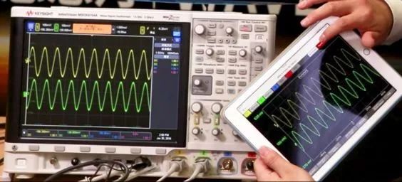
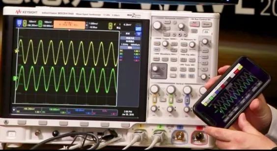
In addition to using the web server for remote control of the oscilloscope, Keysight oscilloscopes also support mobile devices (phones or iPads) for control and waveform observation anytime, anywhere.
2. Remote Control of Oscilloscopes via Automation Control
Remote control and waveform access of oscilloscopes in wired or wireless environments can improve engineers’ testing efficiency to a certain extent. Of course, what truly liberates engineers is to achieve automated testing as much as possible. Below, I will share a software that can quickly implement automated testing without programming.
This software is the BenchVue mentioned a few days ago. Today, we will use BenchVue software to control an oscilloscope to achieve a small automated test:
When the peak voltage input on channel 1 of the oscilloscope reaches 4V or 7V, trigger the oscilloscope to start measuring the current peak voltage and frequency and automatically save the waveform.
The specific steps are as follows ↘↘↘
Step 1: Connect the computer and the oscilloscope, open the BenchVue software, and enter the oscilloscope control interface.
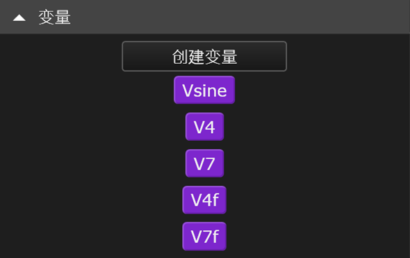
Step 2: Create variables Vsine, V4, V7, V4f, V7f.
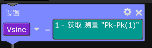
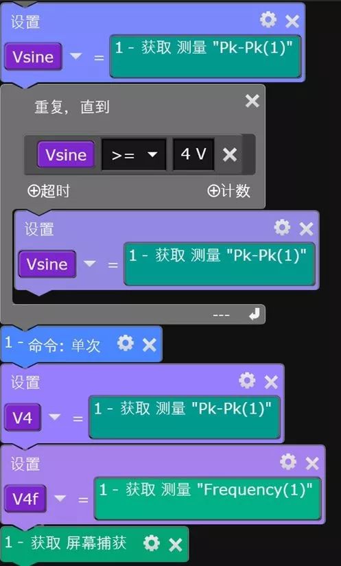
Step 3: Set Vsine equal to the peak voltage measured on channel 1 of the oscilloscope.
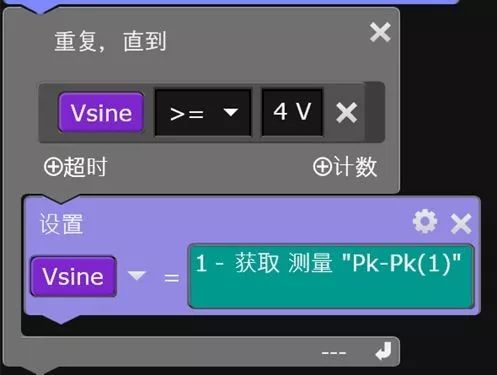
In the “Loop” section, find the “Until” loop, and set the program to continuously obtain the value of Vsine until Vsine is greater than or equal to 4V.
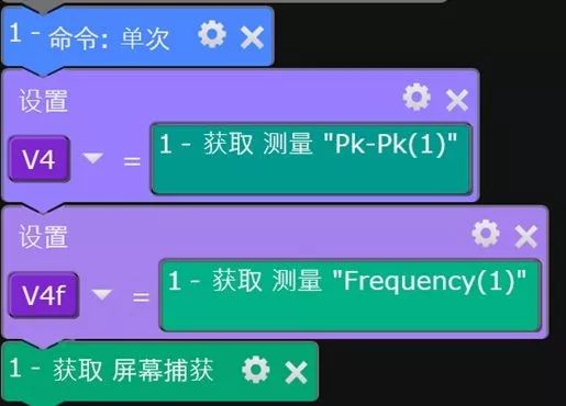
Step 4: After the loop, set the oscilloscope trigger mode to “Single”; the oscilloscope will automatically stop when the loop ends (i.e., when it detects that the voltage on channel 1 is greater than or equal to 4V), then measure the peak voltage at that time on channel 1 and assign it to V4, and assign the frequency to V4f, and after the measurement, save the oscilloscope screen waveform.
Step 5: At this point, the program for the oscilloscope to automatically measure the voltage reaching 4V on channel 1 and save the image has been set up, and the complete program is as follows:
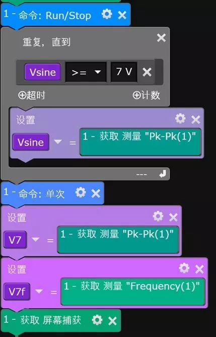
Step 6: Change the oscilloscope status to run, and set up the automatic test and waveform saving for when the peak voltage on channel 1 reaches 7V in the same way.
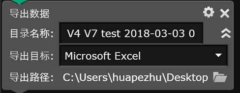
Step 7: Finally, set up the automatic data export, and you can change the exported data, folder path, name, etc.
The automation program is completed, and it only takes 5 minutes to fully implement this automated test program without writing any code. You deserve it.
3. Programming Basics for Remote Control of Oscilloscopes
Remote control of instruments can be achieved using either the software provided by the manufacturer or by programming it yourself. Regardless of the method, you need to set up the environment in advance. It is advisable to list the hardware and software architecture of the automated testing system to avoid missing anything.
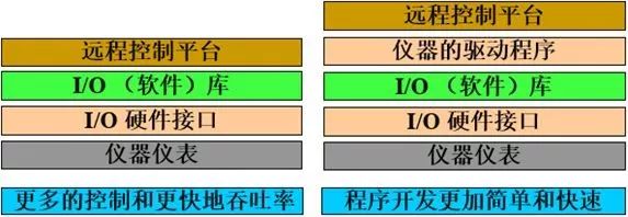
The above image is a block diagram of the hardware and software architecture for remote control of instruments. The bottom layer is the instrument you want to control, followed by the computer that controls the instrument using I/O hardware interfaces. Above that is the I/O software library; some manufacturers provide instrument driver programs, and finally, there is the remote control platform or programming environment.
Each instrument may support different I/O hardware interfaces, commonly including Ethernet, USB, and GPIB. For Ethernet and USB, you only need to prepare Ethernet or USB cables; for GPIB control, in addition to the GPIB cable, you also need to configure a GPIB interface card on the computer.
I/O (software) libraries can be found from the manufacturer or downloaded from their website, such as Keysight’s I/O library, which can be found by searching for IO Libraries Suite on their official website.
Most engineers can find I/O (software) libraries and instrument driver programs on the websites of Keysight (Agilent) and NI. Instrument driver programs encapsulate the main functions of the instrument into subprograms for engineers to call directly. The advantage is simplicity and directness, while the disadvantage is that instrument driver programs may not cover 100% of the instrument’s functions, and may not be optimized for testing throughput.
There are many types of software or programming environments for remote control, commonly including VB, C, C++, VEE, LabVIEW, LabWindows/CVI, Matlab, and Python. Different programming environments correspond to different instrument driver programs. For example, if you are programming in C, you should look for C language instrument driver programs; if you are programming in LabVIEW, you should look for LabVIEW instrument drivers.
If there is no instrument driver program, or if the instrument driver program does not fully meet your needs, what should you do?
In this case, you need to perform low-level programming control of the instrument. Additionally, if you want to optimize the execution speed of the test program, you often need to bypass the instrument driver program and directly control the instrument through low-level programming. At this point, you need to refer to the instrument programming manual. For example, for the Keysight DSOX4154A oscilloscope, you can search for DSOX4154A on the Keysight website, then select Technical Support to find the programming manual and instrument driver program.
The programming manual contains a collection of instrument commands and explanations for each command. It is generally recommended to start from the table of contents of the manual to understand the classification of instrument commands and where example programs are located.
In this example, the programming example is in Chapter 44. In addition to the examples listed in the manual, the manual also indicates that more examples can be downloaded directly from the official website at www.keysight.com/find/4000X-Series-examples . You can directly modify and add based on the example program to achieve the desired functionality.
I hope the above examples have not disappointed you.
One-click to bookmark the article!
As usual, let’s learn while having fun.
Today’s Challenge
Keysight Instruments Lighting Challenge awaits you.
Continuous lottery draws.
See how many instruments you can light up.
Long press to identify the QR code to challenge immediately.
↓↓↓
About Keysight Technologies
Keysight Technologies is a leading technology company dedicated to helping engineering, enterprise, and service provider customers optimize networks, thereby bringing their electronic products to market faster and at lower costs. From design simulation to prototype validation, to production testing and optimization of networks and cloud environments, Keysight provides comprehensive electronic signal testing and analysis solutions. Our customers span the global communications, aerospace and defense, automotive, energy, semiconductor, and general electronics end markets. In April 2017, Keysight completed the acquisition of Ixia, a company with strong capabilities in network testing, visibility, and security solutions. For more information, please visit www.keysight.com


Click “Read the original text” to participate in the continuous lottery activity.