
The Role of Oscilloscopes in Embedded Systems
In embedded system development, oscilloscopes play a crucial role:
-
Signal Observation and Analysis
-
Observe the waveforms of various electrical signals, such as pulse waveforms of digital signals and the changing trends of analog signals.
-
Analyze the stability and quality of signals to determine if there are issues such as noise, interference, or distortion.
Hardware Debugging
-
Detect the working status of hardware circuits in embedded systems.
-
Assist in locating hardware faults, such as abnormal signals, short circuits, and open circuits.
Software Debugging
-
Coordinate with the software debugging process to observe signal changes related to the software.
-
Verify the correctness of software algorithms, such as the processing effects of digital signal processing algorithms on input signals.
Performance Evaluation
-
Measure performance indicators such as signal transmission speed and response time to evaluate the performance of embedded systems.
-
Compare signal changes between different design schemes or before and after optimization to provide a basis for system optimization.
What Operations to Master When Using an Oscilloscope
-
Preparation Work
Select an appropriate oscilloscope based on the characteristics of the tested signal, and prepare the relevant environment. Ensure secure connections to avoid poor contact or interference.
-
Set Oscilloscope Parameters
For example, select the corresponding channel, set the vertical and horizontal scales, choose the appropriate trigger mode and conditions to ensure the oscilloscope can stably display the signal waveform.
-
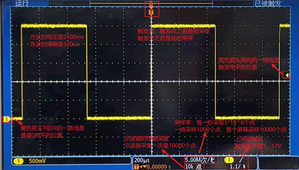
Observe Signal Waveform
Observe the waveform, amplitude, frequency, duty cycle, and other parameters of the signal, and perform analysis. Use measurement functions to obtain more accurate parameter values.
-
Store and Analyze Data
Use the oscilloscope’s storage function to import data into a computer for analysis and processing.
-
End of Use
After use, remember to properly shut down the oscilloscope and store it safely. The person in charge should also perform relevant maintenance work.
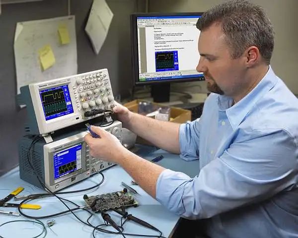
(Image source from the internet)
Practical Use of Oscilloscopes
Debugging Clock Signals in Digital Circuits
-
Connect the oscilloscope probe to the clock signal source and set the appropriate vertical and horizontal scales.
-
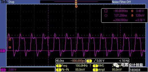
Observe the waveform of the clock signal and check if its frequency meets design requirements. You can use the oscilloscope’s measurement function to directly read the frequency value of the clock signal.
-
Analyze the duty cycle of the clock signal. Ideally, the duty cycle of the clock signal should be 50%. If there is a significant deviation, it may affect system performance.
-
Check the stability of the clock signal. Observe if there are issues such as jitter or drift in the clock signal. If so, further checks may be needed on the clock source, power supply, etc., to determine the root cause of the problem.
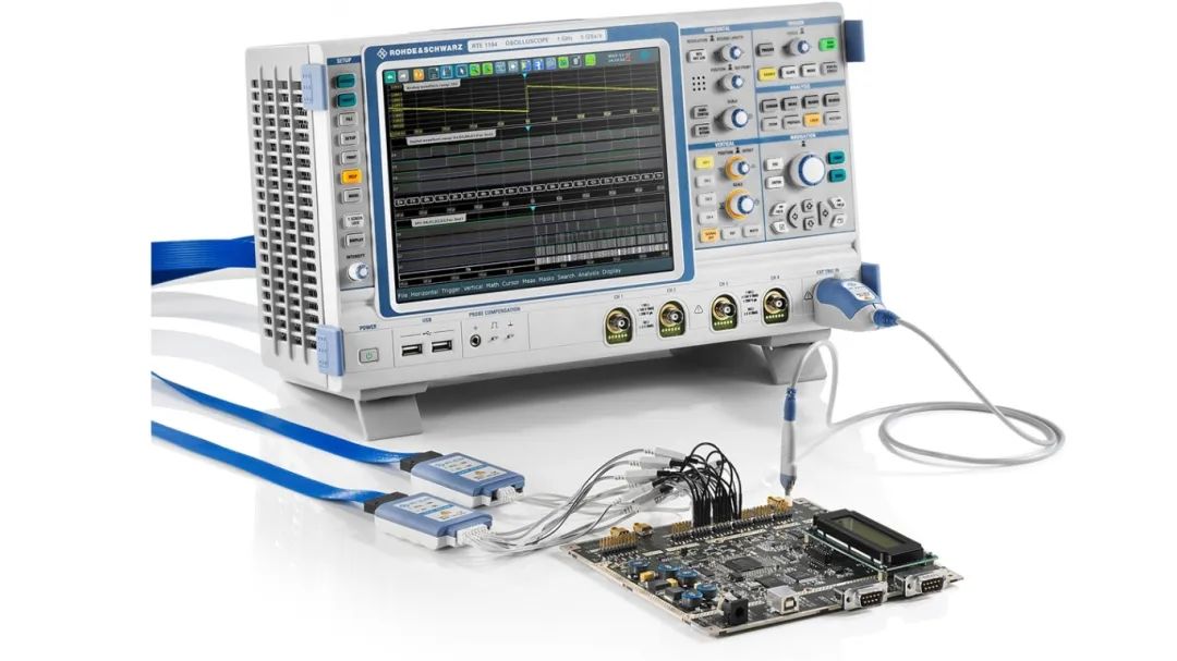
(Image source from the internet)