The template testing feature adds a capability to traditional oscilloscopes: it allows for a quick assessment of whether the input signal is qualified. When an unqualified signal is captured, we can perform actions such as stopping and taking a screenshot. This article will introduce the template testing functionality of the ZDS4000 series oscilloscopes and provide application examples.
 Introduction to the Template Testing Interface
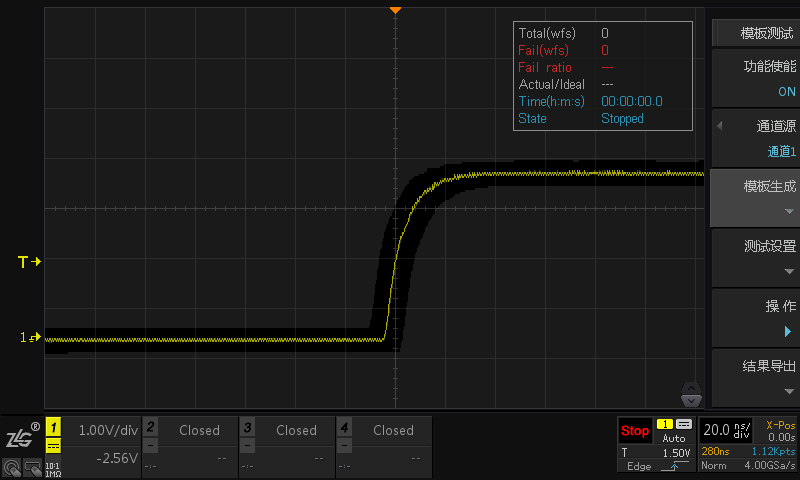
Figure 1: Template Testing Interface of the ZDS4000 Series
In automated testing, the template testing feature is very practical. We can define a standard signal and then set qualified or unqualified regions around the standard signal. By comparing the input signal with the standard signal, we can determine whether the input signal is qualified or unqualified.
Figure 1 shows the testing interface for template testing on the ZDS4000 oscilloscope, where the gray area surrounding the waveform represents the template touch area, which is the unqualified area, while the black area represents the qualified area. As shown in Figure 2, if the waveform touches the template touch area, it will be displayed in red and deemed an unqualified waveform, labeled as “Fail”; if it does not touch the template touch area, it is labeled as “Pass.” The information displayed in the upper right corner shows some status information during the template testing process.
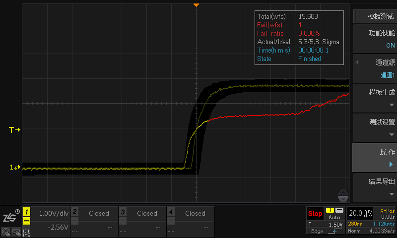
Figure 2: Template Testing Failure Interface
Steps for Template Testing Setup
The steps for setting up the template are as follows:
-
Access the analysis interface by pressing the 【Analyze】 button on the oscilloscope panel, select 【Template Testing】, and turn on the 【Function Enable】 to “ON”;
-
Select the waveform channel to be tested from the 【Channel Source】 menu, as shown in Figure 3:
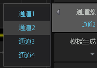
Figure 3: Template Testing Channel Setup
-
Enter the template generation interface by selecting 【Template Generation】. By adjusting the 【Vertical Tolerance】 and 【Horizontal Tolerance】, you can change the size of the template touch area. After adjusting the template touch area, you can generate a template testing area through the 【Generate】 menu. You can also import and export templates using 【Template Import】 and 【Template Export】, as shown in Figure 4:
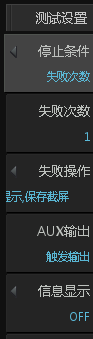
Figure 4: Template Generation Settings
-
Set the conditions for template testing, which specify the actions to take when the input waveform touches the template area. We can set stop conditions, whether to take a screenshot upon touching, sound alerts, etc., as shown in Figure 5:
Figure 5: Template Testing Condition Settings
-
After completing the above settings, we can click 【Operation】 to start the template pass testing. The status information during the testing process can be viewed through the information display menu, as shown in Figure 6:
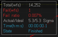
Figure 6: Template Testing Status Information
Application Case of Template Testing
Customer Requirement: Long-term testing of a fluctuating signal around 5V. If the input signal fluctuates beyond the range of 4V to 6V, the customer wants the oscilloscope to capture the anomaly and save a screenshot.
Based on the customer requirement, we can utilize the template testing functionality of the ZDS4000 oscilloscope. We first input a 5V DC signal, then adjust the 【Vertical Tolerance】 to set the upper limit to 6V and the lower limit to 4V, and click to generate the template, as shown in Figure 7. Then, in the template testing condition settings, we can set the 【Failure Action】 to save a screenshot. This way, we can meet the customer’s testing requirements.
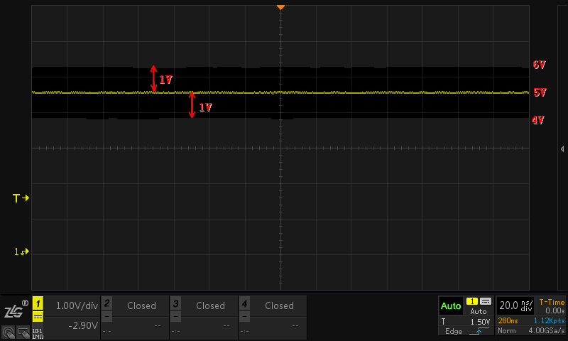
Figure 7: Case Template Area Diagram
Conclusion
This article mainly introduces the template testing functionality of the ZDS series oscilloscopes, providing detailed setup steps and specific applications of template testing in conjunction with customer cases.

If you have any questions, you can:
 Add WeChat ID: zlgmcu-888
Call the official technical hotline of ZLG Zhiyuan Electronics: 400-888-4005.