Why Are Oscilloscopes So Expensive?

Why Are Oscilloscopes So Expensive?

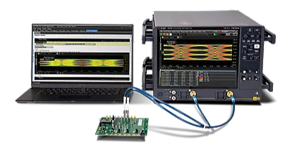
Oscilloscopes Are Simple Yet Complex! But Why Are Oscilloscopes So Expensive? Most cost thousands or tens of thousands, why are they so expensive?
Why Are Oscilloscopes So Expensive?
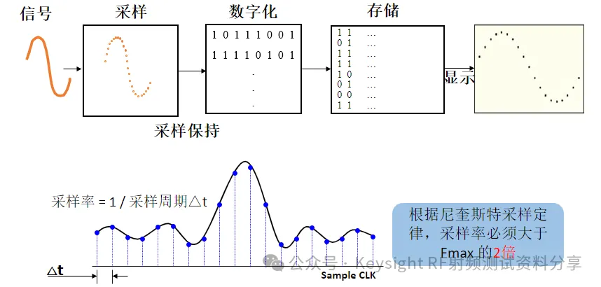
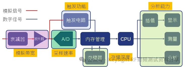
Structure of Digital Oscilloscopes
The Reason Oscilloscopes Are Considered Simple Is That An Oscilloscope Is A Test Instrument That Can Display The Dynamic Waveform Of Voltage Signals. An Oscilloscope Converts Time-Varying Voltage Signals Into Curves In The Time Domain, Making The Invisible Electrical Signals Visible On A Two-Dimensional Plane, Allowing For The Analysis Of The Temporal Properties Of Electrical Signals. Advanced Oscilloscopes Can Even Analyze The Spectrum Of Input Time Signals, Reflecting The Frequency Domain Characteristics Of The Input Signals.
Why Are Oscilloscopes So Expensive?
But Oscilloscopes Are Also Complex!!!
The High Price Of Oscilloscopes Is Mainly Due To Their High-Precision Measurement, High-Performance Sampling Rate, Large Storage Capacity, And Complex Internal Structure. Since The Frequency Of The Measured Signal Can Be Very High, This Requires The Oscilloscope To Be Very Fast. We All Know That The Sampling Rate Determines The Measurement Accuracy Of The Oscilloscope In The Time Dimension (Horizontal).
Why Are Oscilloscopes So Expensive?
Sampling Principles
Why Are Oscilloscopes So Expensive?
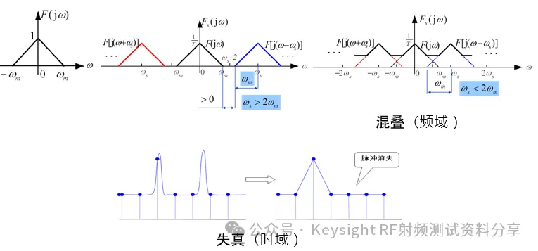
The Nyquist Sampling Theorem – If The Bandwidth Of The Signal Being Measured Is Finite, Then When Sampling And Quantizing The Signal, If The Sampling Rate Is More Than Twice The Bandwidth Of The Signal Being Measured, The Information Carried By The Signal Can Be Fully Reconstructed Or Recovered.
The Precision Technologies And Complex Processes Involved In The Design And Manufacturing Of Oscilloscopes. The Internal Structure Of An Oscilloscope Includes Components Such As Transmission, Attenuation, Amplification, Low-Pass Filtering, Hardware Triggering, Sampling, And Calculation; Each Component Requires High-Precision Design And Manufacturing To Ensure The Final Measurement Accuracy And Performance.
Taking Digital Oscilloscopes As An Example, Simply Following The Sampling Theorem + Calculation, The Sampling Speed Must Reach At Least Twice The Frequency Of The Signal Being Measured. So If I Want To Measure A 10MHz Signal, The ADC Sampling Speed Must Be At Least 20MSa/s, Meaning It Must Read The Values 20 Million Times Per Second. This Speed Is Quite Impressive. High-End Oscilloscopes Have Even More Impressive Sampling Rates.
Why Are Oscilloscopes So Expensive?
Astonishing Sampling Rates Of Oscilloscopes!!!
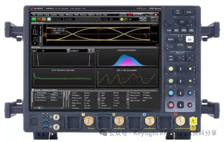
For Example, The Keysight DSOZ634A Oscilloscope Has A Maximum Specified Sampling Rate Of 160GSa/s. What Does This Mean? It Measures The Input Signal Voltage 160 Billion Times Per Second, Which Is Quite Impressive! If Each Sample Generates Just 1 Byte Of Data, It Can Produce 149 GB Of Data In One Second. The Oscilloscope Must Also Analyze And Process This Massive Amount Of Data, Perform Mathematical Calculations, And Convert It Into Graphical Displays. The 149 GB/s Data Generation Rate Is Also An Epic DDoS Flood Attack For An Intel i9, So Oscilloscopes Not Only Have Fast ADC Devices But Also Need High-Performance Processors To Handle The Massive Amount Of Data Returned By The ADC. These Are All Top-Notch Technologies, And The Components That Can Achieve These Functions Are Naturally Expensive!
Reconstruction And Display Of Oscilloscope Waveforms
Digital Oscilloscopes First Store Data In High-Speed Cache, Then The CPU Retrieves The Data From The Cache For Analysis And Display. Most High-End Oscilloscopes Include ASIC Chips, While Keysight Uses FPGAs. The Valuable Part Here Is The FPGA (ASIC), Which Is Slightly More Advanced And Cannot Be Produced Domestically. It Can Be Expected That It Will Not Be Possible To Produce It For A Long Time. Moreover, In Most Cases, The Quantities Of FPGAs And ASICs Used Are Very Small. The Cost Of A Single Wafer Is Known To Everyone, So One Can Imagine How Expensive Each FPGA And ASIC Can Be.
Analog-to-Digital Converters (ADC)
The Measured Voltage Is Converted Into Digital Information Through An Analog-to-Digital Converter (ADC). Digital Oscilloscopes Capture A Series Of Sample Values Of The Waveform And Store Them. The Storage Limit Is Determined By Whether The Accumulated Sample Values Can Depict The Waveform. Subsequently, The Digital Oscilloscope Reconstructs The Waveform. The Bit Depth Of The ADC Determines The Minimum Level Signal That The Oscilloscope Can Detect (Vertical Dimension). Every Oscilloscope Manufacturer Started With ADCs, And The High Cost Is Also Due To The Difficulty Of Design, Which Is Not Exported, And The Quantities Are Extremely Small.
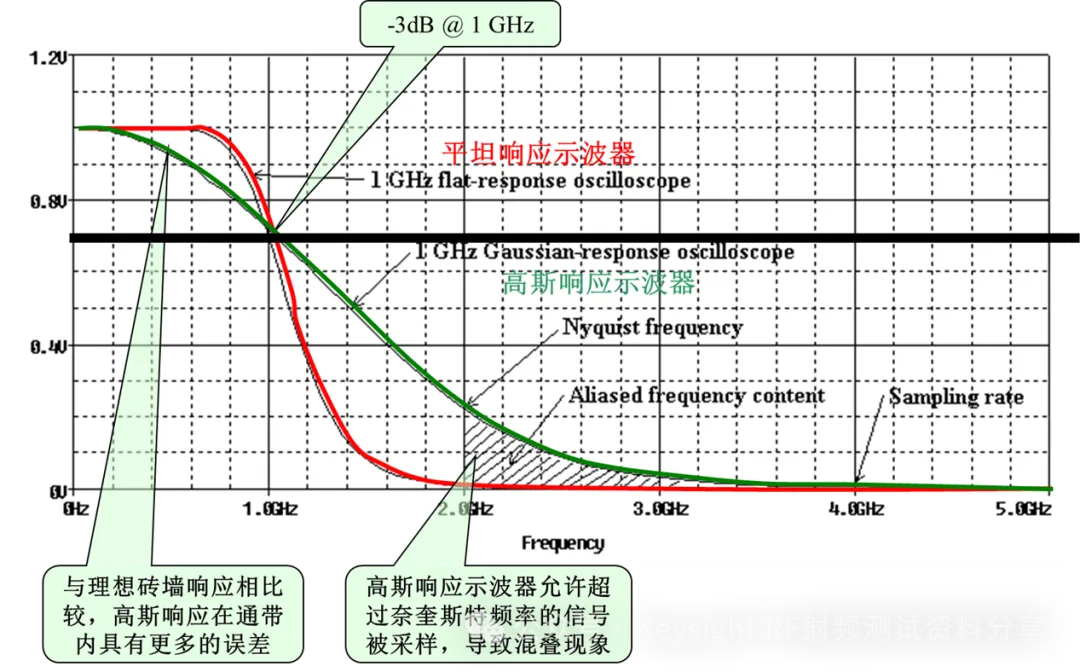
The Importance Of Filters
The Nyquist Frequency (Nyquist Frequency) Is Half Of The Sampling Frequency Of A Discrete Signal System, Named After Harry Nyquist Or The Nyquist-Shannon Sampling Theorem. The Sampling Theorem States That As Long As The Nyquist Frequency Of The Discrete System Is Higher Than The Highest Frequency Or Bandwidth Of The Sampled Signal, Aliasing Can Be Avoided.
Theoretically, Even If The Nyquist Frequency Is Just Greater Than The Signal Bandwidth (But Not Equal), It Is Sufficient To Reconstruct The Original Signal Through Sampling. However, The Process Of Reconstructing The Signal Requires A Low-Pass Filter Or Band-Pass Filter To Filter Out All High-Frequency Components Above The Nyquist Frequency While Ensuring That The Frequency Components Below The Nyquist Frequency Do Not Get Distorted, Which Is Impossible To Achieve. In Practical Applications, To Ensure The Performance Of The Anti-Aliasing Filter, Components Close To The Nyquist Frequency May Be Distorted During Sampling And Signal Reconstruction. Therefore, In Practical Applications, The Signal Bandwidth Cannot Approach The Nyquist Frequency Indefinitely; The Specific Situation Depends On The Performance Of The Filter Used.
Why Are Oscilloscopes So Expensive?
Relationship Between Sampling Rate And Frequency Response
This Filter Must Have An Attractive Frequency Response Curve, Be Very Precise, And Be Difficult To Achieve. The High-Speed Front End Is Naturally Expensive.
Source: Keysight TechnologiesRelated Articles:Super Guide! A Step-By-Step Guide To Using An Oscilloscope How To Measure Current With An Oscilloscope? How To Adjust The FFT Function Of An Oscilloscope? How To Measure Ripple In Power Supplies? This Explains The Frequency Domain And Time Domain, So You Understand! Understand DDR Memory Principles In One Article What Is Transient Response? Experienced Drivers Teach You Signal Integrity Circuit And Communication Testing Common Terms
Oscilloscope – Frequently Asked QuestionsWhat Is An Oscilloscope? An Oscilloscope Is A Test Instrument Used To Capture And Display The Waveform Of Electrical Signals As They Vary Over Time. For Example, It Can Plot A Graph Of Voltage (Y-Axis) Against Time (X-Axis) On Its Display. Oscilloscopes Are Powerful Tools For Designing And Testing Electronic Devices. They Play A Very Important Role In Determining Whether System Components Are Functioning Properly And Which Components Are Malfunctioning. They Can Also Help You Determine Whether New Design Components Will Work As Expected. This Can Be Done By Analyzing Signal Parameters Such As Amplitude, Period, Frequency, Rise Time, Pulse Width, Etc. Modern Digital Oscilloscopes Can Also Perform Mathematical Operations On Waveforms, Such As Fourier Transforms, To Complete Analysis More Quickly.

Why Are Oscilloscopes So Expensive?

What Are The Different Types Of Oscilloscopes? All Modern Oscilloscopes Are Digital Storage Oscilloscopes (DSO), Which Use Digital Signal Processing To Capture And Display Analog Signals. If An Oscilloscope Can Simultaneously Observe These Signals In The Digital Domain, It Is A Mixed Signal Oscilloscope (MSO). If An Oscilloscope Has A Built-In Spectrum Analyzer Function, It Is A Mixed Domain Oscilloscope (MDO), Although This Term Is Less Common. What Are The Uses Of An Oscilloscope? Test Engineers And Developers Use Oscilloscopes To Display, Visualize Graphically, And Analyze Electrical Signals During Research And Development, Verification, Quality Assurance, And Troubleshooting Or Debugging Of Electronic Systems, Circuit Boards, And Integrated Circuits. Oscilloscopes Play A Key Role In Various Applications And Technologies Across All Industries, Including High-Speed Digital Electronics, Optical Communications, RF, Power Electronics, Automotive, Aerospace, And Defense. Oscilloscopes Are Key Testing Instruments For Observing, Analyzing, Or Recording The Behavior Of Electrical Signals. In Electronic Laboratories, Some Specific Use Cases Of Oscilloscopes Include Measuring Voltage Waveforms, Analyzing Electronic Signals, Detecting Unwanted Noise And Crosstalk, And Evaluating Harmful Transients In Power Systems. In High-Speed Signal Analysis, Oscilloscopes Can Measure Signal Integrity By Displaying And Measuring Eye Diagrams, Including Eye Height And Eye Width. Mixed Signal Oscilloscopes Can Help Debug Digital Circuits By Displaying The Logic States And Timing Of Measured Digital Signals. Advanced Oscilloscopes Can Even Help Simulate Ideal Reference Receivers For Transmitter Testing, Use Photoconverters To Measure Fiber Optic Signals, And Analyze RF Signals. Due To Their Versatility, Oscilloscopes Have Many Different Performance Levels And Software Functions Depending On The Application. They Are Indispensable Tools In Electronic Development, Troubleshooting, And Analysis. How Does An Oscilloscope Work? An Oscilloscope Uses Probes Connected To Test Points In A Circuit To Amplify Or Attenuate The Voltage At That Point. The Subsequent Signal Path Depends On The Oscilloscope, But Generally, The Analog Circuit Conditions The Signal, And The Analog-To-Digital Converter Digitizes It For Further Evaluation, Processing, And Analysis. What Is The Difference Between An Oscilloscope And A Spectrum Analyzer? An Oscilloscope Captures And Displays Signals In The Time Domain, While A Spectrum Analyzer Captures And Displays Signals In The Frequency Domain. Sometimes, Oscilloscopes Have Built-In Spectrum Analyzer Functions For Convenient Signal Analysis In Both Time And Frequency Domains. How To Use An Oscilloscope? There Are Many Brands And Types Of Oscilloscopes On The Market That May Look Different, But Most Follow The Same Basic Steps. Here Is A Step-By-Step Guide On How To Use An Oscilloscope: – Connect The Probe: Connect The Probe To The Input Channel Of The Oscilloscope. Ensure A Secure Connection. If You Have An Attenuation Probe, You May Need To Compensate The Probe Until A Perfect Square Wave Is Achieved. – Test The DUT: Connect The Probe To The Device Under Test (DUT) By Connecting The Probe Tip To The Point Of Interest In The Circuit And The Ground Clip To The Common Ground Point On The DUT. – Adjust The Vertical And Horizontal Scales: Use The Oscilloscope Controls To Adjust The Vertical (Voltage) And Horizontal (Time) Scales. This Ensures The Waveform Is Displayed Correctly On The Screen. – Set The Trigger: Use The Trigger Settings To Stabilize The Waveform. The Trigger Helps Ensure The Signal Is Displayed Stably. Adjust The Trigger Level And Type As Needed. – Interpret The Waveform: View The Waveform On The Screen. The X-Axis Represents Time, And The Y-Axis Represents Voltage. Observe The Shape, Frequency, And Amplitude Of The Signal. – Analyze The Waveform: Identify Any Issues Or Anomalies. Does The Signal Perform As Expected? Are There Noise Spikes Or Irregularities? Troubleshoot Any Detected Problems To Ensure Accurate Signal Performance. You Can Use The Oscilloscope’s Features, Such As Cursors And Automatic Measurements, To Assist In Analysis.Source: Keysight Technologies
END

Collection Of Circuit Diagrams

Common Analog Circuits | Operational Amplifier Circuits | Protection Circuits | EMC Standard Circuits | Power Supply Circuit Collection | Practical Control Circuits | Microcontroller Application Circuits | Waveform Generator Circuits | Complete Collection Of Automotive Circuit Diagrams | 555 Circuits | Small Appliance Circuits | 9 Basic Module Circuits | English Abbreviations For Schematics | Circuit Symbols

Basic Introduction

Circuit Basics | Digital Circuits | Basics Of Oscilloscopes | Using Multimeters | Signal Integrity | Ground Knowledge | Embedded Basics | Summary Of STM32 Basic Knowledge | C Language Key Points

Components

Resistors | Capacitors | Inductors | Diodes | Transistors | TVS | Thyristors | MOSFETs | IGBTs | Sensors | Relays | Equivalent Circuits Of Components | Complete Guide To Component Selection | Component Failures

Join The Community

If You Want To Join The Electronics Industry WeChat Group, You Can Scan The Code To Add Our Community Operations. Please Note The Group Direction (A Brief Description Of The Target Group, Such As: Embedded, Market Trends, Etc.)

Why Are Oscilloscopes So Expensive?

Leave a Comment